This thread has been locked.

If you have a related question, please click the "Ask a related question" button in the top right corner. The newly created question will be automatically linked to this question.

UCC28700-Q1: Controller IC doesn't providing switching wave

Part Number: UCC28700-Q1

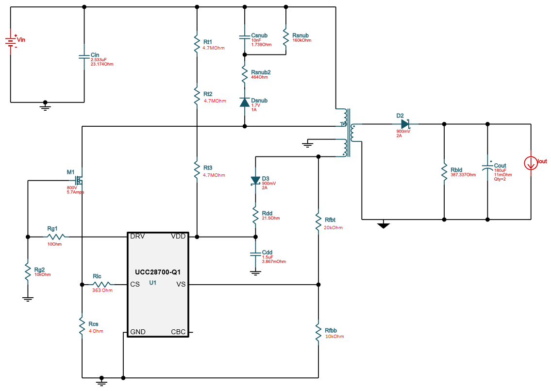
I am using UCC28700-Q1 for DC-DC converter. The designed circuit is same as per the typical application circuit mentioned in datasheet of IC (Page No.17) which is modified for DC to DC converter with Vdd= 12 V.

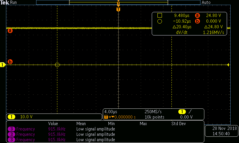
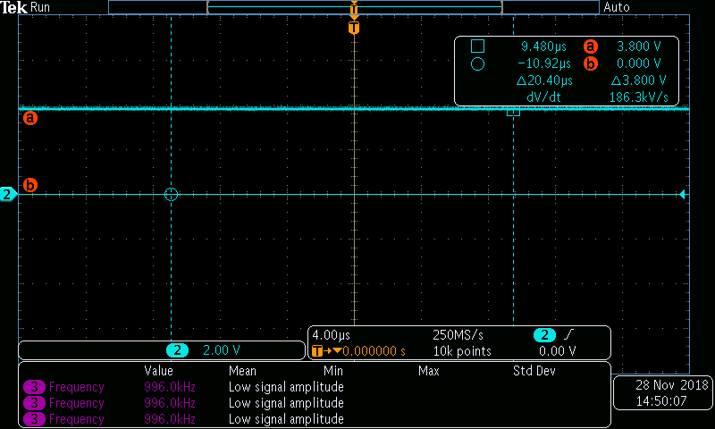
But while testing the circuit, the voltage at Vdd pin of the controller (with respect to ground) is continuously changing between UVLO threshold i.e. 8 to 21 Volts. ( After reaching 21 volts, it again comes back to 8 volts and starts increasing to 21 volts)

Is it the reason behind not providing switching wave? 

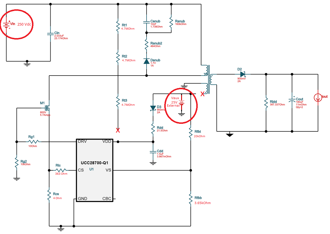
What is the procedure for testing UCC28700-Q1 Controller separately?

  • Hello Harshal,

    Thank you for your interest in UCC28700-Q1.
    When the Vdd voltage is within the VDD turn-ON and turn-OFF threshold, the controller should produce the DRV signals. May you please attach some waveforms for further understanding: Vdd voltage, DRV voltage, VS pin voltage.
    You can test this with attaching a 12V- VDD supply externally and see if the regulation of the output is the problem here. Additionally, you can check the VS pin voltage to make sure the controller is not in OV fault mode.
    Please share your design spec and the schematic diagram of your application.

    Regards,
    Sonal
  • Thanks for the help.

    I have tested the circuit by applying 12V- VDD supply externally and also checked VS pin voltage but still controller does not producing DRV signal.

    Below are some observations:

    1. Voltage at pin VDD w.r.t. ground= 11.7V 

    2.Voltage at pin VS w.r.t. ground= 4.05V

    Design Specifications:

    Vin (min)= 250 Vdc

    Vin (max)= 400 Vdc

    Vout= 12 Vdc & Iout= 0.8 A 

    Maximum desired switching frequency: 100 KHz

    Targeted efficiency: 90%

    Discontinuous conduction mode with maximum duty cycle (Dmax)= 0.465

    Diode voltage drop=0.5V

    Transformer turns ratio (NPS)= 22:1

    Transformer turns ratio (NPA)= 22:1

    Number of turns at Primary= 222

    Number of turns at Secondary= 10

    Number of turns at Auxiliary= 10

    I have also attached the schematic of the same.

  • Hi,

    Apologies for my mistake there, the VDD turn-ON threshold is 21V(typing error:12V, in the previous message), Please increase the external supply to 21V to enable startup.
    Interesting thing to notice is if the controller is not producing any DRV signal there should be no voltage at the VS pin because this pin senses the output. Can you please attach the VS pin waveforms? I would also like to look at the VDD and DRV pin waveforms at startup.
    If the controller is still not producing DRV signals then we should check if the controller is in any fault state.

    Regards,
    Sonal
  • Hello,

    As per your suggestion, I have applied 25 Volts VDD supply externally and also checked the VS pin voltage. But still controller does not producing DRV signal.

    I couldn't able to record the waveforms but below are some observations with VDC(in)=250V & VDD(external)=25V

    1.Voltage at VDD pin w.r.t. ground= 24.2V

    2.Voltage at VS pin w.r.t. ground= 3.8V

    3.Voltage at DRV pin w.r.t. ground= 0V 

    Following is the circuit diagram of the Test Setup I am using:  

  • Hello,

    It is hard to understand why this is not operating in open loop condition, have you tried to swap the controller? The only reason why the controller should not produce DRV is when under a fault condition, it is not line fault and nor OV fault. To check the overcurrent fault may you please check the voltage at CS pin(it is a very sensitive pin, I suggest probing it)

    In order to understand the problem better please share the waveform of VDD(21V), DRV, VS pin.

    Regards,

    Sonal

  • Hi,

    The waveforms of VDD (25V), VS, DRV & CS are as follows:

    1. VDD

    2. VS


    3. DRV


    4. CS


    Is it possible to test UCC28700-Q1 separately just by applying VDD (25V) & testing DRV signal? If yes, then what should be the status of VS & CS pin. I think VS will be applied directly via calculated voltage divider but how can we ensure the status of CS pin? 

  • Please help me with that
  • Hello Harshal,

    Apologies for the late response.

    Yes if you are providing a constant DC at VCC the controller should generate DRV pulses, the thing to note here is if VS pin is in regulation and CS pin voltage is well below the OC threshold the only fault left that might cause the controller to not switch is the line or temperature fault.
    Also this CS waveform is not very helpful please zoom in to look at the right shape and the amplitude of the signal.

    Can you check the primary current and the temp on the controller? is it possible that the controller might be damaged during your previous testing? I would recommend replacing the controller to be sure.

    Regards,

    Sonal
  • Hello Sonal,

    How can we control Line or temperature fault?

    And also while testing, I noticed that current through ground (GND pin) wire of controller is increasing upto 3A.

    Regards
  • Hello Harshal,

    If you see 3A in the GND pin then the controller is definitely dead, you can see for yourself if the supply voltage is right and the power demand on VS pin is high then there is nothing stopping the controller to generate DRV pulses. 

    Please use the excel calculator attached to quickly revisit your spec and check your component values and replace the controller. 

    Regards,

    Sonal

  • Hello,

    I have tested the circuit for modified values as per excel file with new controller but still there is a current of around 3A in GND pin of the controller and no DRV signal.
  • Hello Harshal,

    We can have a webex call if that suits you better, it will be faster that way.

    Regards,
    Sonal
  • Hello Sonal,

    The problem of overcurrent at GND is resolved. It was because the use of non isolated oscilloscope for the measurement.
    Now, the switching controller proving DRV signal for very small inetrval ( i.e. When Voltage at VDD is varring between 9 to 21 Volts).