This thread has been locked.

If you have a related question, please click the "Ask a related question" button in the top right corner. The newly created question will be automatically linked to this question.

TPS2549: Divider mode

Genius 4720 points
Part Number: TPS2549
Other Parts Discussed in Thread: PMP40269

If Divider2 device is attced to USB,Does this part change current limit value according to Divider number automaticaly ?

  • In DCP_auto mode, the part will automatically detect Divider 3, 1.2V short, and BC1.2. The part does not support Divider 1 and Divider 2 modes.
  • Chuck-san

    Thank you for your reply.

    1.Please let us know TPS2549 behavior when Divider1 or Divider2 device is attached to USB.

    2.If you have part which support Divider1 and  Divider2 and Divider3,please let us know about it.

    Regards,

    Kura

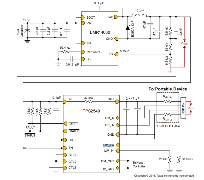
  • 1. The TPS2549 should fall into CDP mode and provide a current limit of 1.5A.

    2. I will have to do some research to answer this question. All of my devices are either divider mode 1 and 2 or divider mode 3. I will be on Paid Time Off on Monday and the rest of today, so I will get back to you on Tuesday with any devices that support all 3 divider modes.

    Regards,
    Chuck
  • Kura-san,

    I was able to research our portfolio further and we do not have apart that supports all 3 divider modes. There are several parts that support divider 1 and divider 2 and a few parts that support divider 3.

    I am going to mark this thread as resolved, so please confirm it is resolved or simply respond back to this thread and it will automatically re-open.

    Regards,
    Chuck
  • Chuck-san


    Thank you for your reply.


    I'd like to confirm my understanding.


    If Divider2 device attached to USB,TPS2549 enters to CDP mode and provide a current limit of 1.5A(not 2A).

    So this part does not support Divider2.

    Is my understanding correct ?

  • Kura-san,

    The device does not support Divider mode 2, so the part will transition into CDP mode as you understand.

    The current limit will be set by RILIM_HI which is required to provide a minimum of 1.5A, but is allowed to support more and still meet the standard. The downstream has to be able to charge with 1.5A, so in practice, you are correct that the CDP will operate at 1.5A.


    Please click issue resolved if you don't have any further questions, but feel free to update the thread if you need any further help.

    Regards,
    Chuck
  • Chuck-san

    Thank you for your support.

    They will use TPS2549 at following conditon.

    DCP mode
    support 2.4A

    so I send below reference design to them.
    PMP40269
    www.tij.co.jp/.../tidruw1.pdf

    They don't use FAULT, STATUS,CS pin.
    Please let us know pin treatment of CS pin in this case.
  • Kura-san,

    I have reviewed the schematic and I see that ILIM_LO is connected to a 20K Ohm resistor to ground. This is not correct, ILIM_HI should be connected to the resistor in this case.

    I believe the the CS pin may be left unconnected in this case, but I want to confirm with the design team to be certain.

    I respond back with the final answer for the CS pin as soon as possible.
  • Kura-san,

    I have confirmed that if the cable compensation feature is not utilized, it is best to float the CS pin.

    Please click the resolved button if this fully answers your questions, or simply respond and I will address any additional issues.

    Regards,
    Chuck
  • Chuck-san

    >ILIM_HI should be connected to the resistor in this case.

    Does this mean that also CTL3 should be connected to Vin?
    Is CTL3 pull up resister value 10kohms ?

    Can EN pin be connected to Vin directly?
  • Kura-san,

    >ILIM_HI should be connected to the resistor in this case.

    Does this mean that also CTL3 should be connected to Vin?
    >> Yes
    Is CTL3 pull up resister value 10kohms ?
    >> Yes
    Can EN pin be connected to Vin directly?
    >> Yes, but use a 10K pull-up resistor.

    Please click the resolved button if this fully answers your questions, or simply respond and I will address any additional issues.
  • Kura-san,

    I have moved this into the TI thinks resolved category. If you feel that I have resolved all of your questions, please click the resolved button or feel free to ask me any further questions you might have.

    Regards,
    Chuck
  • Chuck-san


    Thank you for your reply.


    Based on your advise,They change following point from above circuit.


    CTL3 is connected to Vin with 10kohms.

    EN pin is connected to Vin.

    ILIM_HI is connected to the resister.

    CS is floating.


    In this situation,if divider2 device is attached to USB,does this device  enter to CDP mode ?

    Is current limit 1.5A automatically?

  • Kura-san,

    I believe that the configuration that you desire is shown in the specification.

    This configuration will work as follows:

    First it will present Divider mode 3 at 2.4A current limit (This can be changed by updating the value of the resistor connected to ILIM_HI.

    Then it will detect a BC 1.2 advertisement and present a DCP contract at 2.4A current limit (or the current limit of the ILIM_HI resistor)

    If this fails, then it will present 5V at SDP current limit set by the ILIM_LO resistor.

    I believe that this is the functionality that you have described in this thread.

    If this fully answers your question, then please click the customer thinks resolved button or ask me any further questions that require clarification.

    Regards,

    Chuck

  • Chuck-san

    I would like to get your advice for attached confuguration.

    This is DCP mode,and they don't use FAULT,STATUS,CS.

    ILIM_LO is open.

    ILIM_HI is connected to 19.1kohms.(to set 2.8A)

    (1)

    In this case ,please let us know part behavior when Divider1 is attached.

    (How much current can they charge Divider1 in this configuration ?  )

    (2)

    In this case ,please let us know part behavior when Divider2 is attached.

    (How much current can they charge Divider2 in this configuration?  )

    (3)

    Should they connect ILIM _LO to resister ?

    (4)

    47uF x 2pcs Output capacitors are recommended in  your datasheet.

    Can they use 100uF 1pc capacitor as output capacitor ?

    Circuit configuration.pptx

  • Kura-san,

    1 and 2 will behave the same. If a very old apple or other device that does not recognize Divider mode 3 (These are very rare in the market), then the port will transition through the DCP state machine. It will try DCP shorted and then DCP 1.2V modes. If either of those work, then it will operate as a BC1.2 charger with a 2.8A current limit. If no DCP mode works, then it will operate as a SDP with a 2.8A current limit. The down stream device should respect the BC1.2 current limit of 1.5A and the SDP current limit of 0.9A.

    3. If you are not utilizing the auto-switch features and will always DCP mode with ILIM bit set high, then this pin may be floated.

    4. The can utilize a single 100uF capacitor. Two capacitors are recommended to lower the ESR and improve total system performance, but the difference will be negligible.

    Regards,
    Chuck