This thread has been locked.

If you have a related question, please click the "Ask a related question" button in the top right corner. The newly created question will be automatically linked to this question.

LMV431: Transfer function of TL431 and opto coupler feedback using a UCC2897 component

Part Number: LMV431
Other Parts Discussed in Thread: TL431,

Hi developers,

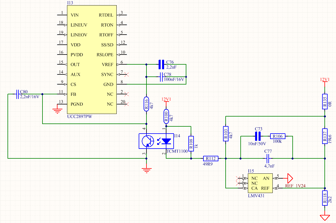
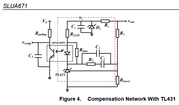
I'm using this circuit in my compensator.

Do you have reference to this circuit using a UCC2897 component?
I'm have difficult with transfer function and my PSU is unstable at times.
The project use an opto with CTR really large (50% at 600%). Can it is a problema?


Best regards!

  • Hi Hernani,

    We have several reference designs with the TL431 and the UCC2897 . These are located in the TI Designs section.
    www.ti.com/.../toolssoftware
    Most of these designs do not show the design process but they do have schematics that show their compensation networks.
    If the PSU is unstable, I believe the compensation network could have issues. It might be necessary to lower the UGB to cross at a more stable side.
    Check out the video below for more information
    training.ti.com/power-tips-compensating-isolated-power-supplies


    -Marcoo
  • Hi, Marcoo.

    I saw this references and my circuit is similar this circuits.

    Please, look my BODE plot for 120W@12VDC.

    My margin stabilize is 75° in 1635 kHz, but even so my PSU is unstable at times.

    When I switch the opto (CTR = 50% at 600%) to another with better CTR (CTR = 80% at 180%), the my PSU is stable.

  • Hi Hernani,

    Higher CTR optocouplers are typically used with low bias currents. At 1-2mA bias with the TL431, a lower CTR optocoupler can be used.
    Typically there are drawbacks with the higher CTR optocouplers like response time. It would be interesting to see the phase margin with 2 different optocouplers.
    See the following blog for more details on CTR as it depends on biasing.
    www.edn.com/.../Make-sure-your-optocoupler-is-properly-biased
    Overall the CTR does affect the response of the system and should be used to calculate the proper biasing current. If your circuit is more stable with a lower CTR optocoupler, then I would use that. Is there a reason you want to use a higher CTR device?

    -Marcoo
  • Hi Marcoo

    Thank you so much for your answers.

    The use of the opto with a large CTR is due to past productions.

    I'll check the information. But i think that my phase it will be bad working only in RLED and RFB.

    My PSU has a frequency of the 120 kHz. Do you see problem if my cut frequency is 1.600 ~ 1.700 kHz? The theory recomends 1/5 to 1/10 of the PSU frequency.

    Regards
    Hernani.

  • Hi Hernani,

    Is this project using a LMV431 or a TL431?
    I can't comment on the cutoff, typically it comes down to the transients and how much UGB you want. The more UGB the better but if its too high you start getting noise.
    One of the dominant poles of the compensation network does come from the opto which is around 5khz. You should be able to get a higher cutoff frequency.

    -Marcoo
  • Hi Marcoo,

    I did not understand the term 'UGB'. Can you explain, please?


    My project is this:


    I changed the opto 'I14' to HMHA2801AR2V (80 =< Gain >= 160) and my project started working again.

    The BODE plot in this configuration is:

    Do you think it's good?

    Regards

  • Hi Hernami,

    I believe you have a lot of room to play with. I believe one of the issues is you have a compensation network for a TL431 higher Iq device on your LMV431 which is a low Iq device.

    For example, you do not need R108 because that is a biasing resistor for TL431 devices and doesn't apply for LMV431.

    You are crossing over the 0 gain frequency with a 80 degree phase margin which is good but you have some room to play with.

    You can decrease C77 and push out the pole C77 has to get a higher cross over frequency.

    An easier method is to look at our LMV431 designs

    check out:

    http://www.ti.com/product/LMV431/toolssoftware

    and

    http://www.ti.com/tool/PMP7932

    -Marcoo

  • Hello Marcoo,


    In my experiences, I hade seen that this is possible. However, the gain is good (cutoff ~ 4 kHz), but the phase is bad ~ 30 ° and the transformer of PSU also stayed really hot. Then I returned the orignals components to PSU.


    I also switched the opto to another of darlington type (600 =< Gain >= 800), but it is impossible to measure the BODE graph and the PSU presented an audible noise.


    Best regards!

  • Hi Marcoo,

    I adjusted my circuit. Could you see the results, please?

    The phase margin and gain margin are good in all results?

    Regards!

  • Hi Hernani,


    I compared your results to other wide Vin, 12V out designs and the phase and gain seem to be similar. I cannot guarantee how your system will perform since there is more factors than the gain/phase but the phase is >45 and the cross over frequency is >1Khz which is good.

    I compared it to this design:
    www.ti.com/.../tidubr3.pdf

    -Marcoo
  • Hi, Marcoo.

    Many thanks for your help and review!