This thread has been locked.

If you have a related question, please click the "Ask a related question" button in the top right corner. The newly created question will be automatically linked to this question.

TPS65910A3EVM-583: EVM VDIG1, VDIG2 & VAUX33 output voltage rails issue

Part Number: TPS65910A3EVM-583
Other Parts Discussed in Thread: TPS65910, USB2ANY, IPG-UI

Customer is using TPS65910A3EVM-583 EVM for evaluation. 

They observed no output at:- VDIG1, VDIG2 & VAUX33. J10 & J8 are installed on the EVM. Any additional settings required to generate all PMIC outputs ?

Need your help to debug same. 

Have kept customer in BCC for direct response & to add further details.

  • Prahlad,

    How are the BOOT1 and BOOT0 pins configured (headers J17 and J16)? In order for the EVM to behave like a TPS65910A3 version, it needs BOOT1=VRTC (logical 1, J17 set to "HI"), and BOOT0=GND (logical 0, J16 set to "LO"). This will force the device to load the settings from EEPROM which allows it to behave as outlined in the TPS65910Ax User's Guide for AM335x Processors (www.ti.com/.../swcu093f.pdf).

    If BOOT1=0 and BOOT0=0 or BOOT1=0 and BOOT0=1, then the device will behave as it is outlined in the TPS65910 datasheet.

    Also, the PWRHOLD jumper needs to be installed on header J20, set to "HI".

    The inputs to most of the converters are set to "VCC IN" by default (J7, J8, J9, J10) so that the whole EVM can be powered from a single power supply.


    If you are still having issues after checking these jumpers, I can confirm all of the default jumper settings on an EVM that I have in the lab.
  • The default jumper positions on a new TPS65910A3EVM-583 are as follows:

    PWRHOLD (J2) = HI
    SLEEP (J19) = LO
    CKSYNC (J18) =HI
    EN1 (J14), EN2 (J13) = HI
    VDDIO (J11) = VIO
    VBACKUP (J6) = GND
    J21, J22 = jumper installed
    VCC6 (J10), VCC5 (J7), VCC3 (J8), VCC2 & VCC4 (J9) = VCC IN

    BOOT0 (J16) = LO
    BOOT1 (J17) = LO

    It is my understanding that you would need to press the push-button (POWER ON, S1) in order to power-up all the rails when BOOT1=0, BOOT0=0 according to the power-on sequence in the TPS65910 datasheet.

    If you change BOOT1 to HI, the device will load default values from EEPROM and power-on without a push-button press.
  • I have verified the jumper positions and they are as expected.

    BOOT1:0 = 00

    I also pressed the push button S1 after power up, but :-

    1. No output at:- VDIG1, VDIG2, VAUX33 (without load)

    > J10 is installed and 2-3 are connected. R6 is mounted correctly.

    2. Not fixed output at VDD3  (i.e. it follows input voltage) (without load)

    > As per datasheet "Note 3: If VDD3 boost is used, VAUX33 must be set to 2.8 V 
    or higher and enabled before VDD3". 

     And as per EVK user guide also "For correct functioning of VDD3, first VAUX33 
    must be enabled at 3.3V and then VDD3 should be enabled using the appropriate 
    register settings."

    VAUX33 is NOT generating ( see point 1), I think that's why VDD3 is NOT fixed. 

    Please suggest.

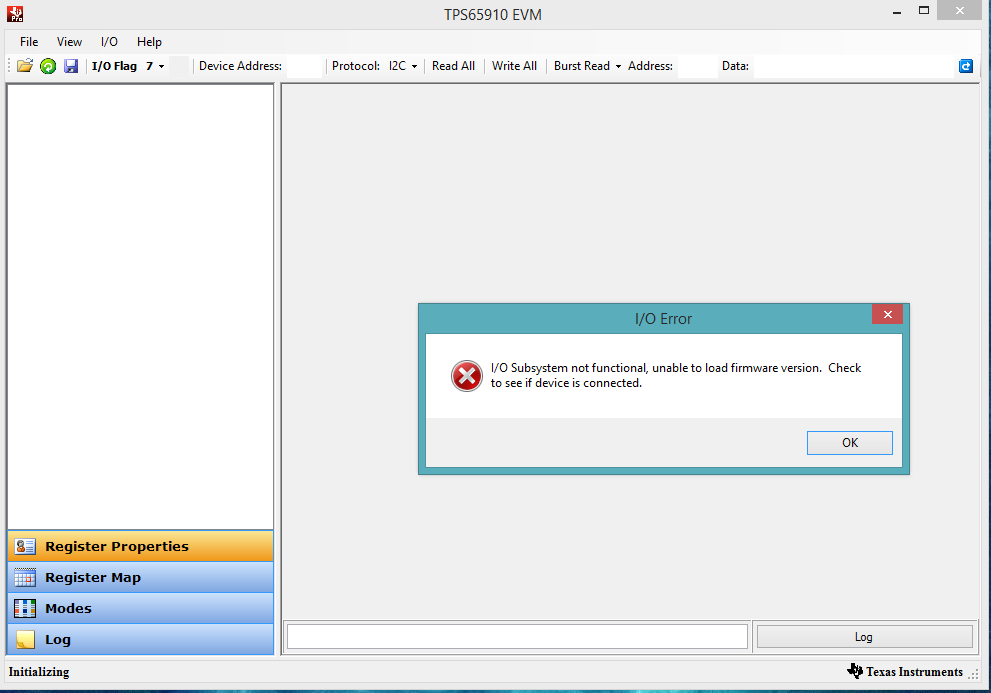
  • Now I connected TI USB Interface adapter to J1 and used "TPS65910 EVM Software". There is one error as I open EVM software (See image). As I connect adapter, there is NO output voltage except VDD3 (which follows input voltage).

    Is anything wrong I am doing?

      0

  • Pratik,

    What USB adapter box are you using? There are two (2) variants:

    • USB2ANY - works with IPG-UI software (this is the preferred hardware adapter and software to use for the TPS65910A3EVM-583)
    • USB-TO-GPIO - works with GUI for TPS65910 Power Management IC – Legacy  (this is the LEGACY software that is not supported anymore)

    It looks like you are using the legacy software, which will only work with the older USB-TO-GPIO adapter. If you have a USB2ANY adapter, the legacy software will not work and this could be the cause of your error. 

  • Hi Brian,

    I was using USB-TO-GPIO with GUI for TPS65910 Power Management IC – Legacy

    1. Which is software currently supported for this EVK and USB to GPIO?

    2. I used "USB Adapter EVM" software (available at www.ti.com/.../USB-TO-GPIO) and try to read 0x34 from device add 0x2D (45). But I got data = XXh and ACK/NACk = ERROR. Message in HELP -> About -> Adapter not attached.

    Please help.

  • Pratik,

    I think you misunderstood a previous suggestion I made on booting up the device correctly:

    The default jumpers positions of BOOT1/0 (headers J16/J17) are:
    BOOT1 = LO
    BOOT0 = LO
    This makes the device behave like the TPS65910 datasheet definition, which is not correct.

    You need to change them to:
    BOOT1 = HI
    BOOT0 = LO
    To make the device behave like a TPS65910A3 device for the AM335x processor family.
  • Thanks Brian,

    By Setting BOOT1:0 = 10, Except VDD3  all other voltages are available. VDD3 follows input voltage.

    Please comment.

  • Pratik,

    For VRTC, it is possible the VRTC voltage is correct initially, but it has dropped due to the low-power mode of the TPS65910A3. See Note 1 on page 5 of the TPS65910Ax User's Guide for AM335x processors:

    "The default mode of the VRTC LDO regulator before the OTP loads is the low-power mode. If the current load exceeds 0.1 mA before the VRTC pin is 1.8 V and the OTP loads, then the VRTC voltage may not reach 1.8 V and the device stays in the NO SUPPLY state."

    The TPS65910A31 is a variant that is identical to TPS65910A3 except that the VRTC supply is in high-power mode during power-on.

    You will need to monitor VRTC on an oscilloscope when you apply power to the EVM, and see if VRTC turns on but then collapses. VRTC should always be on. I do not think the rest of the system could power on if VRTC has collapsed, so this description does not make sense to me. See the 

    For VDD3, you will need to additionally install jumpers J21 and J22 for VDD3 to power-on properly. The expected voltage of this boost converter is 5V. However, Table 2 on page 5 of the same User's Guide says that VDD3 should be OFF because it is not controlled by the sequencer.

    VDD3 will need to be enabled by I2C, and you can use the IPG-UI with the USB2ANY adapter to control the PMIC by I2C. This is the preferred software & hardware for controlling this EVM.