This thread has been locked.

If you have a related question, please click the "Ask a related question" button in the top right corner. The newly created question will be automatically linked to this question.

LM1117: LM1117LD-3.3/NOPB Center Tab connection

Part Number: LM1117

Hi E2E,

Good day!

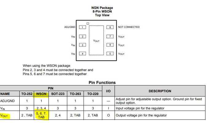
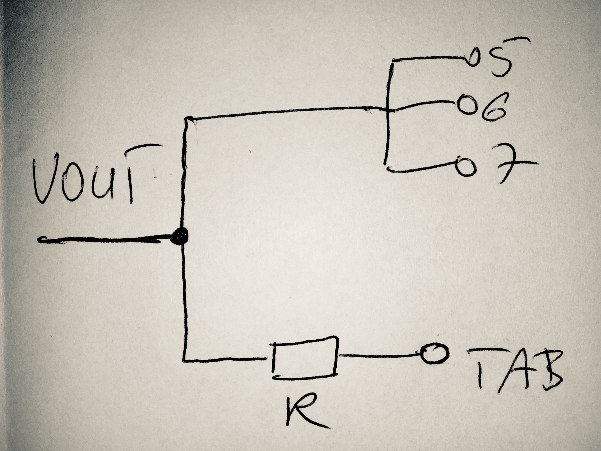
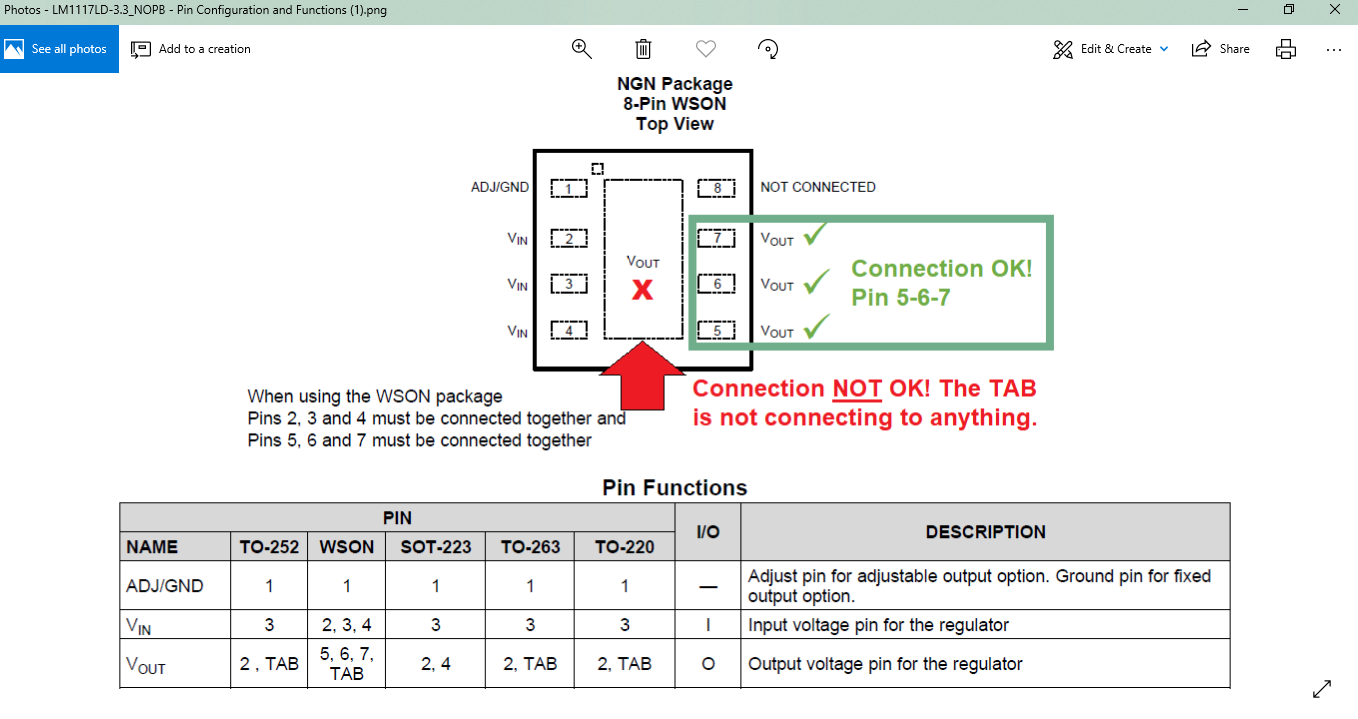
We have a customer asking if the center TAB of LM1117LD-3.3/NOPB is connected to Vout-pins 5, 6, 7 ?
Because actual parts when measured shows NO connections. This is WSON package.
Below image shows customer's concern.

Thank you in advance for the help.

Best Regards,

Art

  • Hi Art,

    The TAB is internally connected to pins 5, 6, and 7 so it is important that the only net the TAB is connected to is Vout.

    Leaving the TAB floating will primarily impact the performance from a thermal point of view. The TAB is the primary path for heat to exit the LM1117.

    Very Respectfully,
    Ryan
  • Dear Art and Ryan,

    According to the TI datasheet of the component, the TAB and pin 5-6-7 should be internally connected. We know that, however there is no connection between the TAB and the output pin 5-6-7 on the actual components. We removed some parts from the assembled boards and we simply measured the part's continuity for these pins with a digital multimeter. The worrying thing is that we experienced the same in case of UNUSED parts as well. That is why it is clear this is not a design issue of the PCB or an assembly problem. Both of you confirmed that the TAB and pin 5-6-7 should be on the same net but this is not the case. Is this a manufacturing problem of the parts then?

    Best regards,
    Tamas
  • Hi Ryan,

    Thanks for the quick response on this.

    However the customer has reported that for unassembled components (not connected to the boards), there is no connection between the TAB and pins 5,6,7.

    Is this normal?

    Appreciate your support on this.

    Best Regards,

    Art Mecina
    Texas Instruments Customer Support

  • Hi Art and Tamas,

    Similar to the thermal pad connection on many other linear regulators, the TAB has an electrical connection to the internal die. In both cases this is not a low impedance connection. In the case of LM1117 this connection is to Vout and is intended to improve the thermal performance only.

    Very Respectfully,
    Ryan
  • Dear Ryan,

    Thank you for your answer.

    However, this raises further questions because this information is not included in the TI datasheet. We think the TAB shouldn't be marked as Vout as the other outputs in this case and it should be clearly described that the TAB cannot be loaded.

    Can you comment on this?

    Best regards,
    Tamas
  • Hi Tamas,

    There is an electrical connection to Vout; therefore, the TAB must be marked to be connected to Vout. It may not be connected to any other voltage. This follows the industry standard for marking the TAB (sometimes referred to as "thermal pad") for WSON packages.

    Very Respectfully,
    Ryan
  • Dear Ryan,

    I do not want to chase you but we still can not accept the answer.

    Can you tell us where can we find in the component datasheet that the TAB can not be loaded and the function of the TAB is not equivalent to the other Vout pins (5, 6, 7)?

    Best regards,
    Tamas
  • Hi Tamas,

    While we do not state that the TAB is functionally equivalent to the pins, we followed industry standards by stating that pins 5, 6, and 7 as well as the TAB are connected to the Vout node.

    The LM1117 is designed, tested, and characterized for the TAB and pins 5, 6, and 7 to be connected to the copper on the PCB (Vout).  As such, in order to achieve the performance depicted in the datasheet, the TAB and pins 5, 6, and 7 must be connected to the copper on the PCB (Vout).

    Very Respectfully,

    Ryan

  • Dear Ryan,

    According to your previous statements and as you wrote in case of the TAB that this is not a low impedance connection, we have drawn a simple schematic about the LM1117 Vout connections.

    Can you confirm that this is correct?

    Can you also tell us what standard you followed exactly what you mentioned in your last reply?

    Thank you in advance.

    Best regards,

    Tamas

  • Hi Tamas,

    You are correct that there would be additional electrical resistance between the TAB and the internal Vout node.

    While I am not aware of a specific standard such as a JEDEC document to point to, this is a common practice throughout the semiconductor industry. The pin configuration table does state to tie all Vout pins and the TAB to Vout. This is the way that the linear regulator was designed, tested, and characterized to be operated. This practice of simply noting the net name for a TAB or thermal pad is common throughout the industry. Typically the TAB or thermal pad would be tied to GND; however, since LM1117 does not have an internal GND reference Vout was used.

    Very Respectfully,
    Ryan