This thread has been locked.

If you have a related question, please click the "Ask a related question" button in the top right corner. The newly created question will be automatically linked to this question.

TLC5957: How to input GSCLK

Part Number: TLC5957

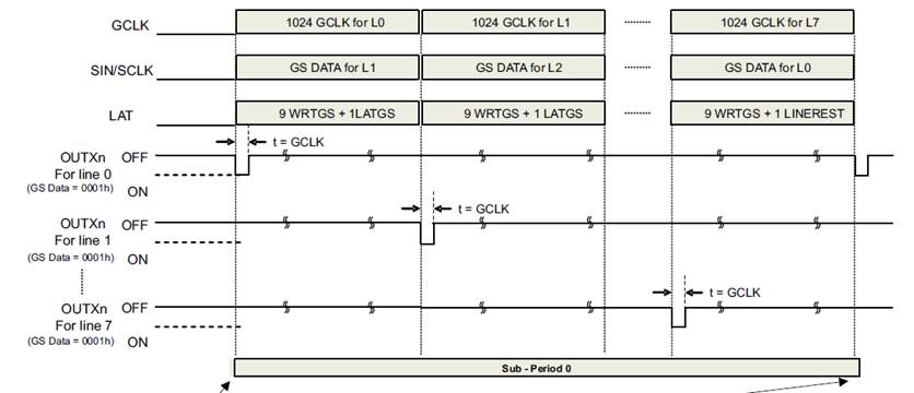
From spec. description, we need to input 2^N clock in one sub-period for one Line as GSCLK.

What will it effect If we input more than 2^N clock?  (OUTXn turn off?)

In practice, it's easy to input GSCLK with "fix frequency" and hard to input with "fix clock count".

Do you have any suggestion about this situation?

  • Hi, Sean,

    Do you use multiplexing?
  • We need to think about both multiplexing or single line cases.
    will the suggestion be different for those cases?
  • Hi, Sean,

    For single line case, you can use continuous GCLK input and don't need to count the GCLK number.

    For multiplexing, it's better to input the fixed GCLK count and switch the line control FETs at the same time. If you can't input the fixed count of GCLK, you can also use continuous GCLK. But the concern is that the refresh rate is not that high. And this is determined by your GCLK frequency.

    What's your GCLK freq?
  • Hi Kenneth,

    For single line case, why we can just use continuous GCLK input?
    It seems TLC5957 doesn't have Auto_Repeat Mode, isn't it?
    what will happen when GCLK counter run over 2^N? will OUTn turn off?

    For multiplexing, if we use continuous GCLK, why it will effect the refresh rate? how it's related to GCLK frequency?
    And the same question: what will happen when GCLK counter run over 2^N? will OUTn turn off?

    The max GCLK frequency we can input is 27MHz.

    Thanks!
  • TLC5957 has Auto Display Repeat. Please refer to datasheet. So it will repeat after 2^N GCLKs.

    If you only have one single line, you don't need to control the GCLK number to achieve the sequence in the User's Guide 3.7.3 The Whole Operation Sequence.

    If you can control your GCLK, you can use the similiar sequence in 3.7.3 which divide the whole frame to 64 sub-periods(10bit-PWM, repeat 2^(16-10) times). If you input continuous GCLK, you can only switch the line after the 65536 GCLKs and the whole frame will only has one sub-period. So that's the difference of the refresh rate.

    But if you use 16 bit PWM there's no big difference.
  • Another thing is sometimes the SCLK frequency is more slower and it may also affects the refresh rate.

    As you know you need to send the next line data when you display the current line, but the writing time is longer than the dislay time. So you can always use continuous GCLK and use the SCLK to calculate the fresh rate.
  • Hi Kenneth,

    For 3.7.3 Example (10 bits mode, 8 lines), is the 64 sub-period necessary? if so, why?
    or it's just a example, the sub-period can be any number?

    As you say "If you input continuous GCLK, you can only switch the line after the 65536 GCLKs and the whole frame will only has one sub-period."
    => 1. Does it apply to 16 bits PWM only? or other bit modes applied too? Why?
    2. Why whole frame will only has one sub-period? Could we only input 65536 GCLKs in one frame?

    Thanks,

    Sean
  • It's just an example, and you can use 9-16 bits using poker mode. As you know the internal GS Counter is 16 bit, so the total display period(or one frame period) is 65536 GCLKs. If you choose N bits (9=<N<=16), the sub-period number is 2^(16-N).

    If you use 12 bit for example, you don't need to use 65536 GCLKs for a sub-period, but 4096 GCLKs.

    If you use 16 bit PWM, it means each sub-period you need to input 65536 GCLKs and the whole display period is also 65536 GCLKs since the chip has internal 16 bit GS Counter. So there is only one sub-period in the whole display period(or one frame period).
  • Hi Kenneth,

    Q1. As GS Counter is 16 bit, if we enable "Auto Display Repeat" & use continuous GSCLK, below two options which one is correct?
    1. The OUTn PWM On/Off signal will auto repeat according to PWM bit count
    ex: 16 bits PWM will repeat every 2^16 GSCLKs
    12 bits PWM will repeat every 2^12 GSCLKs
    10 bits PWM will repeat every 2^ 10 GSCLKs
    ...
    2. No matter the PWM bit count, it will all auto repeat PWM On/Off signal every 2^16 GSCLKs
    => if this is the case, when using 10 bits PWM for example, will OUTn turn off between GSCLK 1024 th ~ 65534 th?

    Q2. As GS Counter is 16 bit, if we enable "Auto Display Repeat" & use continuous GSCLK, is the GS data only updated & applied every 65535 GSCLK
    NO MATTER the PWM bits count?
    (if so, i think it's the reason you say how it effect the refresh rate)

    Q3. If we enable "Auto Display Repeat" & use continuous GSCLK, Do u suggest we use as higher frequency as better?
    will the frequency we input GSCLK effect the LED drive result?
  • Sorry for the confusion.

    Q1. Option 1 is correct. If you use 12 bits, it repeats every 2^12 GSCLKs.
    Q2. You can use poker mode to send N(9-16) bits data, and the total period is 2^N GSCLKs. Thus you can improve the refresh rate.
    Q3. The output PWM frequency = GSCLK Frequency/2^N * 128. So higher GSCLK results to higher OUTPUT PWM frequency.
  • Q2. You can use poker mode to send N(9-16) bits data, and the total period is 2^N GSCLKs. Thus you can improve the refresh rate.
    => From User Guide Table 4 FC Regitster Bit Assignment:
    "All data in the 1st GS DATA latch are copied to the second GS DATA latch until GS counter reaches the maximum count value of 65,536."
    it seems the GS data only updated & applied every 65535 GSCLK no matter use Poker Mode or not?

    Q3. The output PWM frequency = GSCLK Frequency/2^N * 128. So higher GSCLK results to higher OUTPUT PWM frequency.
    => Why multiply 128?
  • Q2: If you use poker mode, the total GSCLK is corresponding changed. Refer to 3.4.3 Poker Mode for GS Data.
    Q3: In TLC5957 ES-PWM control, the entire display period is divided into 128 display segments. Refer to 3.5.3 Multiplexed Enhanced Spectrum (ES) PWM Control.