This thread has been locked.

If you have a related question, please click the "Ask a related question" button in the top right corner. The newly created question will be automatically linked to this question.

TPS65265: Dynamic Response

Part Number: TPS65265

Hi,

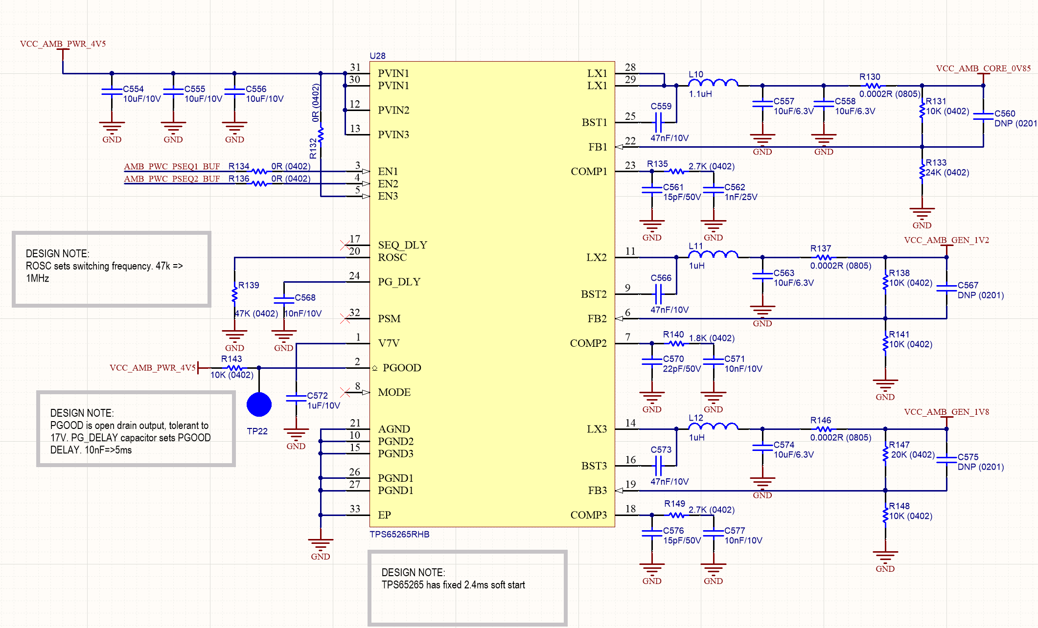
I am testing on a board that uses the TPS65265 to generate several voltages. 

One of our supplies generated by the TPS65265, which has a nominal voltage of 1.2V, has a nominal current load of 50mA, but has transient loads of ~400mA.

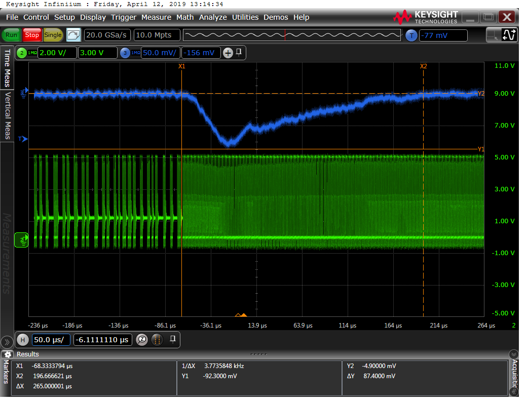
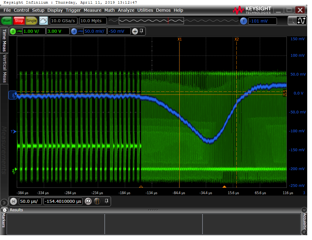
We have found that there are dips on the 1V2 supply that last several hundred microseconds, and have been observed to be ~150mV from the nominal value. These deviations are causing issues for digital circuitry powered by the TPS65265

In the attached oscilloscope screenshot, green channel 2 is the voltage on the LX pin, DC coupled. Channel 3 in blue is the output voltage, AC coupled.  We are using the TPS65265 in PSM mode and it is clear that the TPS65265 changes mode when this transient load takes place. It appears that the TPS65265 is not regulating the output voltage for some time after switching from PSM mode to CCM mode. Are there any known issues with this?

Thanks,

Tom Perman

  • Hi, Tom 

    Are you testing TPS65265 EVM? 

    If not, could you send me the schematic? 

    From the waveform, TPS65265 working behavior is normal. 

    The big dip is mainly caused by converter slow loop response, in other words, the loop bandwidth is too small to response the load transient.  

    Suggest to enlarge Rc to increase bandwidth. 

    Based on experience, you can try Rc=50kohm. 

  • Hi Zao,

    We are testing our own circuit, please see our schematic attached below. The waveform shown is from the second channel, generating voltage VCC_AMB_GEN_1V2. 

    We tried forcing the regulator into CCM mode by pulling the PSM pin to 0V. IN CCM only mode we no longer observed these dips. 

    Thanks,

    Tom 

  • Hi, TOM

    Comments:
    1. Your used Rc is too small, suggest to set R135=R140=R149=10kohm, which can enlarge loop bandwidth in PSM, it will reduce the output dip voltage.
    2. The switching frequency in FCCM mode is continuous, FCCM has wider bandwidth than PSM, so the dip is disappear.
  • Hi Zhao,

    Responses:

    1. I tried changing R140 to 10K as you suggested. I recorded the dip voltage again, which is reproduced below. Although the dip has been reduced in amplitude to only ~90mV it has not solved the issue. It still takes ~250us for the nominal voltage to be reached again.

    2. In the screenshot below the regulator has switched into CCM mode within ~10us of the start of the voltage dip. For the majority of the dip (remaining 240us) the regulator is operating in CCM mode, and so i would expect the higher bandwidth associated with this. When the regulator switches to CCM from PSM is there an initialisation time required before the CCM mode is fully operational?

    Thanks,

    Tom

    Blue - AC coupled 1V2 supply

    Green - LX2 DC coupled. Shows the transition between PSM and CCM clearly. 

  • Hi, Tom 

    Comments: 

    1. Continue to increase Rc to 30kohm, or 40kohm, or 50kohm to further reduce the dip voltage. 

    2. For Vout recovery time, suggest to reduce Cc(C571 and C577) to 2.2nF or 1nF.