This thread has been locked.

If you have a related question, please click the "Ask a related question" button in the top right corner. The newly created question will be automatically linked to this question.

LP5912: LP5912-5.0 VS TPS7A4700

Part Number: LP5912
Other Parts Discussed in Thread: ADS114S08, TPS7A47

Hello,

I am designing an instrumentation system based on ADS114s08 and I need some help to decide which LDO could serve me better, in terms of cost and quality.

I found that TPS7A4700 is much more expensive, has lower noise and a better PSRR in high frequencies.

In my design I am using a low cost DC-DC and the switching frequncy of the DC-DC is between 100-300 KHz.

Will using the TPS7A4700 have an advantage in my case? and in practice how the power supply noise will show up in the system?

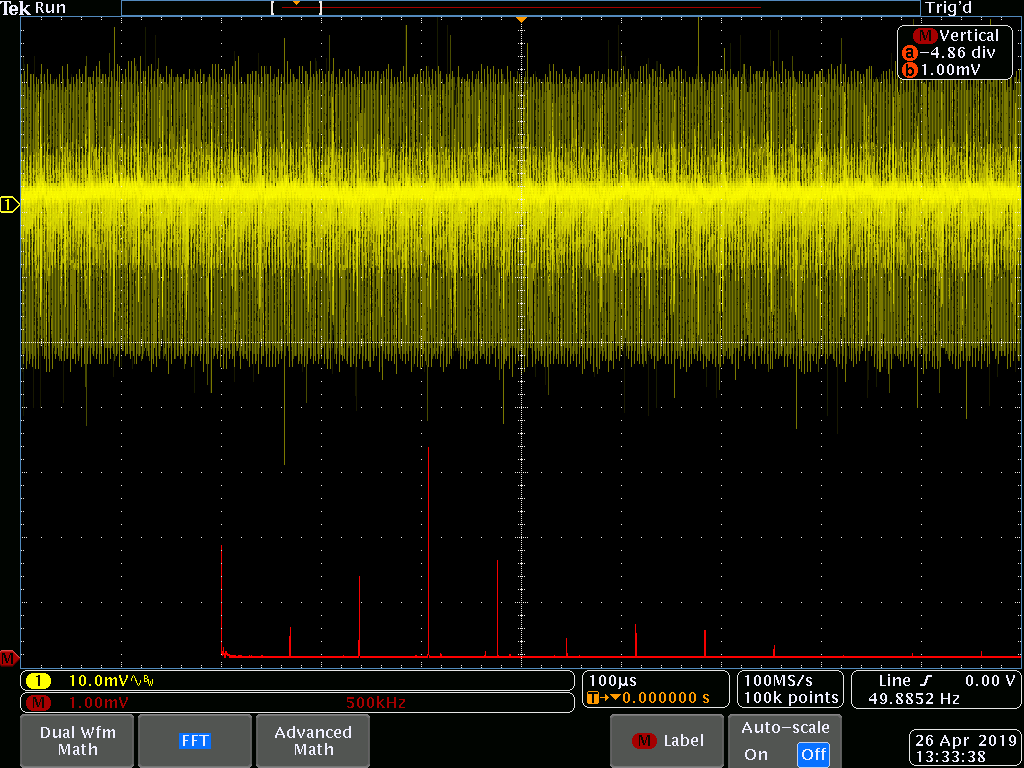
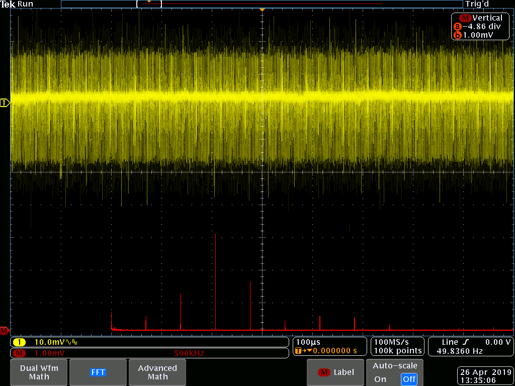
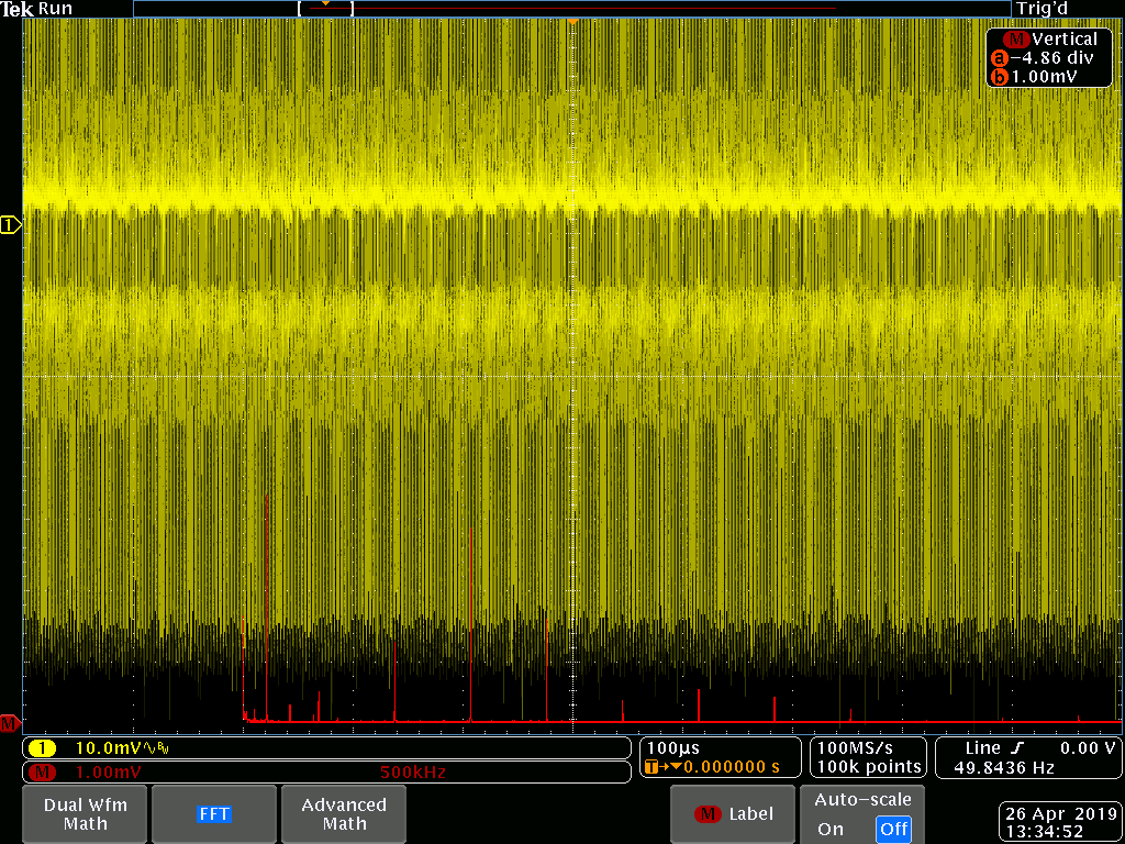
If I have two prototypes with different LDOs, is there an easy way to tell which is performing better?

I have MDO4000 scope but I am not sure if it can help in this matter, I tried to use it in AC coupling mode and compare the two LDO outputs but I didn't notice any difference.

Regards,

Mahmoud

  • Hi Mahmoud,

    LDOs with good PSRR performance can be used as a filtering after the DC-DC. That's why TPS7A47 has listed "Post DC-DC Converter Regulation and Ripple Filtering" as one of its targeting applications. For noise-sensitive application, noise after the LDO will include two parts, the noise from the supply of the LDO after filtering (the capability of filtering is decided primarily by the PSRR specification) and the internal noise from the reference that LDO generates by itself.

    In order to see which LDO performs better, you can look at the ripple on your DC-DC output and comparing it to the output of the LDO after filtering to see if it's acceptable to your applications. You can also try to use your MDO4000 in spectrum analyzer mode and get the noise amplitude plot over frequency. You can easily see the difference between different LDOs. The question then becomes how sensitive your application to noise.

    Regards,
    Jason Song

  • Hi Jason,

    I used the MDO4000 to do some analysis on the LDOs output, please find the results attached.

    Is this the difference you would expect to see? what do you suggest to eliminate the 1.1 MHz noise?

    My ADC output data rate is between 500-2000 SPS, will this noise effect my measurement?

    Regards,

    Mahmoud

    LP5912-5.0

    TPS7A4700

  • Hi Mahmoud,

    According to the screenshot, you applied the FFT on the signal, however, FFT's resolution is not as good as using the built-in spectrum analyzer. We don't have a MDO4000 in our lab but I believe there should be a RF channel you can use. The built-in spectrum analyzer will give you a better pictures on the amplitudes of the noise you have on your output.

    Based on our previous communications, the DC-DC frequency is up to 300 KHz. I am a little confused why the highest noise amplitude in your FFT is at 1.1MHz. I would suggest you to use the RF channel to get more accurate readings.

    For your ADC questions, I am not an expert on that topic. You will need to post this questions for the ADC guys.

    Regards,
    Jason Song
  • Hi Jason,

    There is no RF channel in my MDO4000.

    The power source of my DC-DC is coming from another DC-DC which running at 350 KHz that is where the 1.1 MHz came from.

    Actually my DC-DC could run between 100-300 KHz, after checking it is running at 125 KHz and it was rejected by the LDO please find the attachments (they show the signal before and after the LDO), what I am not sure about is why the 350 KHz & 1.1MHz was not rejected by the LDO as well.

    Can you suggest a way to get ride of those spikes?

    Regards,

    Mahmoud

    Signal before TPS7A4700

    Signal After TPS7A4700

  • Hi Mahmoud,

    Can you share the schematic of your TPS7A47 prototype board? The reason I am asking is because TPS7A47 has decent PSRR values at 1MHz if you have enough headroom between Vin and Vout. The PSRR@1MHz may drop significantly if the headroom becomes less or close to the dropout values.

    Assuming at the condition TPS7A47 was used, the datasheet PSRR is 60dB@1MHz. You would expect the signal amplitude at 1MHz dropped to 1/1000 of your input signal at 1MHz. From your scope-shot, the 1MHz amplitude has little drop which makes me to suspect the LDO may be set in a configuration that has very low PSRR performance at 1MHz.

    Regards,
    Jason Song
  • Hi Jason,

    Please find the schematic attached.

    The prototype has two LDOs and I am assembling only one of them on the board.

    Regards,

    Mahmoud

    TC_Schematic.pdf

  • HI Mahmoud,

    I've reviewed the schematic for the connections of TPS7A47 and it looks okay. It seems to me that the noise power you see at the output is being injected through cross-talking with other traces or cables, can you check your layout and if it is possible, can you also share a photo of your actual setup for the measurement? The LDO has around 60dB PSRR at 1MHz,based on the FFT, the amplitude has no change before and after the LDO. That's why I am guessing there is possibility that the 1.1MHz noise might be injected to the input and output of the LDO from other sources.


    Regards,
    Jason Song

  • Hi Jason,

    I am using a barrel ground tip on the MDO4000 probe, with AC coupling at 10mV setting. and I am measuring on the output and input capacitors.

    Actually, if I place the probe close to the board without connecting it to anything, I can see that noise 366 KHz 732 KHz 1.1MHz I think that means it is a radiated noise coming from the master board.

    My board is stacked to master board which has 366 KHz DC-DC.

    In this case is there any method to filter out this noise from my board, or it must be solved in the master board itself.

    Regards,

    Mahmoud

  • Hi Mahmoud,

    The noise can be filtered by having proper filters in the system. The common way is to add capacitors with a resonating frequency in the range close to your main noise frequency; the idea is to provide a low impedance node to discharge the noise power at the noise frequency. Murata has lots of applications notes on how to filter noise with capacitors. I personally find them very helpful. If you search online, there are lots of other solutions that may or may not work for your application. You may also need to think how to shiled your sensitive traces and fully understand the tolerance of the noise that the system allows to have.

    I am glad you were able to confirmed where the noise were coming from and if you need any other questions on the LDO, please let me know.

    Regards,
    Jason Song