- Ask a related questionWhat is a related question?A related question is a question created from another question. When the related question is created, it will be automatically linked to the original question.
I'm doing two projects using tps92692. I have a question if I should use them in the buck-boost or boost configuration?
Project 1:
Input:
Vin: (Min: 6V-Typ: 12V-Max: 16V)
Output:
3 LEDs in series
VLED: (Min: 2.75V-Typ: 3.25V-Max: 3.55V)
Vout: (Min: 8.25V-Typ: 9.75V-Max: 10.65V)
I LED output current: Typ: 1A - Max: 1.2A
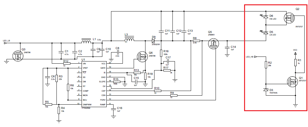
Project 2:
Input:
Vin: (Min: 6V-Typ: 12V-Max: 16V)
Output:
2 LEDs in series, but sometimes only one will be active or both will be active. For this I will use a FET.
VLED: (Min: 11.6V-Typ: 13.6V-Max: 14.8V)
Vout with 1 LED active: (Min: 11.6V-Typ: 13.6V-Max: 14.8V)
Vout with 2 LEDs actives: (Min: 23.2V-Typ: 27.2V-Max: 29.6V)
I LED output current: Typ: 1A - Max: 1.2A