This thread has been locked.

If you have a related question, please click the "Ask a related question" button in the top right corner. The newly created question will be automatically linked to this question.

TPS62136: In Constant current regulation - woult it stable with

Part Number: TPS62136
Other Parts Discussed in Thread: TPS62135, , INA250, OPA348

Hello

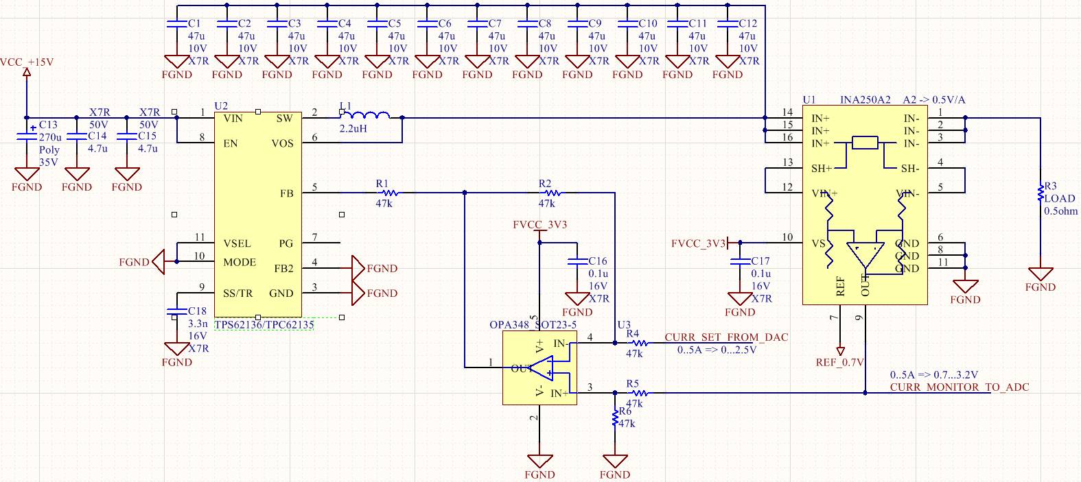
Proj. description: to design resistive  switching wire heater psu with regulated current. The load resistance is extremely low

Load resistance from 0.5 ohm

- Current regulated from 0.2 to 4.0 Amp

- Max output volatge at least 5V.

- Least possible Voltage ripple

- Maximum effciency for least heat dissipation (will work in sealed/closed/isolated env.)

output voltage requirement is to swing to ner 0V asthis wire heater would need about 0.1V output to feed 200mA in to 0.5ohm.

There is a pair questions:

1. what is the difrence  between TPS62136 and TPS62135.

2. would the TPS62136 be stable with added V to I conversion on INA250 and OPA348?   specified INA250A2 BW ~50kHz and OPA348 ~1Mhz.

  • Hi Karne,

    The TPS62135/6 differ only in their switching frequency. TPS62136 is slower, which makes it a little bit more efficient.

    If you want lowest ripple, you should tie the MODE pin to Vin to get forced PWM mode. Efficiency at lower load currents will be lower than in PFM mode.

    I don't understand why you need low ripple for this application. A few mV of switching ripple should not impact the amount of heat produced in the heater, I think. As well, all those 47uF caps exceed the maximum recommended output capacitance and do not help reduce the ripple--you are far past the point at which adding more C helps.

    Finally, if your heating element allows it, you could connect it on the high side and remove the INA and amp. This configuration is shown in Figure 86 and detailed in this reference design for the previous generation device: http://www.ti.com/tool/PMP9762
  • Thaks for suggestion, will tie MODE to Vin.
    All this will float on 30kV acceleration voltage (this is why sealed and no ventilation)and ripple may affect electron beam quality.
    What max amount of C on output I could put here?

    Regarding INA250 - it features 2mOhm sense resitor - which translates in to much less heat in it. Plus I need to monitor current on ADC and set current via DAC. I don think this easily achievable otherwise.

    Since TPS62135/6 uses insternal loop compensation my concern is could INA250 and OPA348 alter TPS62135/6 internal feeback loop stability? In other words do you think INA250 and OPA348 are fast enough not to make TPS62135/6 unstable?
  • Hi Karne,

    The maximum output cap is written on page 4 of the D/S with a more detailed discussion on page 13, 14, and 32.

    You can simulate and bench test your proposed configuration to see if it meets the specific needs of your application. High side sensing like this can be done, and you need to confirm if it meets your application's performance needs with your slew rates, operating point changes, etc.