This thread has been locked.

If you have a related question, please click the "Ask a related question" button in the top right corner. The newly created question will be automatically linked to this question.

BQ24610: Problems about charging

Part Number: BQ24610

Hi,

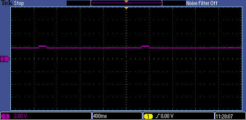
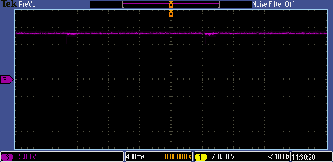
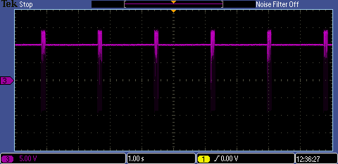
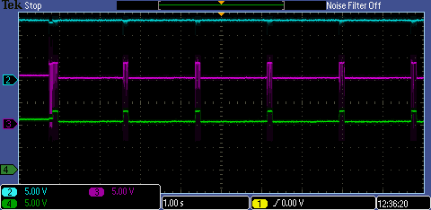
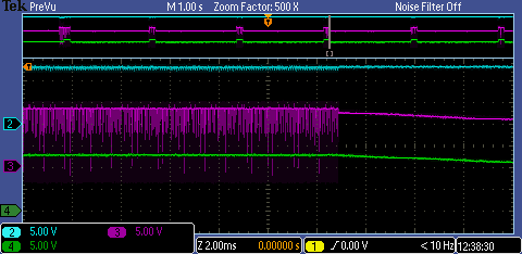
When the CE is enable, refering to waveforms on Page 12(BQ24610 datasheet), I see that VCC、VREF、REGN signals are normal. But PH and LODRV are abnormal. After the chip enters the charging mode, it lasts about 200ms and then it quits the charging mode. Because of CE enable, it happens every 2 seconds cyclically. The STAT1 LED blinks. Whether some conditions are triggered, it makes bq24610 to enter the charging mode and quit immediately. I read Section 9.3.7,but I didn't know how to solve it.

What is the reason? What should I do?

Thanks!

Regards!

  • Hi,

       STAT1 blinking means the charger is entering and exiting a fault condition. Table 2 in the datasheet shows STAT pin definition in normal operation and fault conditions, so first you want to make sure your test setup is not violating any of those conditions. To debug this please tell me your test conditions (input voltage, battery voltage, system load etc) as well as include the scope shots of abnormal behavior. 

  • Hi,

    The relevant parameters are as follows.

    (1) Input voltage : 13.7V;

    (2) Battery charge voltage : 12.6V(Configuration resistor 100K and 510K);

    (3) Battery charge current : 0.836A(Configuration resistor 100K and 5.5K);

    (4)Precharge and termination current : 0.08A(Configuration resistor 100K and 2.5K);

    (5)Safety timer: 9.3h (CTTC-0.1uF);

    Refering to Section 9.3.7, there are eight conditions to enable charging.

    (1) CE is connected to VREF(3.3V);

    (2) VCC is 13.7V(>3.85V UVLO, >1.55V VCCLOWV);

    (3) ACFET turns on, the device is not in SLEEP mode;

    (4) VCC is 13.7V(<VACOV 32V);

    (5) CE is enable after at lease 30-ms delay after initial power up;

    (6) REGN is 6V, and VREF is 3.3V, after CE is enable;

    (7) TSHUT is not valid(Room temperature);

    (8) TS pin is 1.8V(no fault).

    I don't know what causes charging repeatedly. The charge is over at the beginning. It happens 2 seconds cyclically.

    Most test conditons have been list above. Please help to analyze possible reasons and tell me what to do next.

    Thank you very much!

    Best regrads!

  • Hi,

       Can you take a waveform of VCC, SRN, STAT1, and PH on one scope capture? This will help me analyze with more information.

  • Hi,

    The waveforms are shown above.

    The signals from 1 to 4 waveforms are: STAT1, VFB, VCC, PH.

    Please help to anylyze this problem.

    Thank you very much!

    Best regards!

  • Hi, Kedar

    The test waveforms have been uploaded. Are there other waveforms that need to be provided? 

    If you have time, please help analyze the problem. 

    Thank you very much!

    Best regards!

  • Hi,

      Can you overlay these scope captures onto one plot? The timing here is important with how the signals relate to each other. Also for VFB can you offset the signal by a DC value, so we can see this signal with higer resolution?

  • Hi,Kedar

        Before CE is enable, I measured some signals voltage value. VCC: 13.681V, SRN: 10.421V, VFB: 1.69V.

        After CE is enable, the waveforms were recorded as follows.

        Channel 2(blue): VCC

        Channel 3(pink):  PH

        Channel 4(green) : SRN

        All configurations are as described earlier.

        Please help to analyze the problem. What should I do next?

        Thank you very much!

  • Hi, Kedar

    The test waveforms have been uploaded.

    If you have time, please help analyze the problem. 

    Thank you so much!

    Best regards!

  • Hi,

       If possible can you try increasing the input voltage as a check? Another step is to monitor ACDRV on a scope at your current VCC to see if there is any oscillation (I am looking to see if ACDRV is ever transitioning between VCC and VCC-6V). It also looks like you are measuring the DC value of SRN before CE but SRN voltage jumps to near your set charge regulation point (5V scale is hard to see accurately, include a cursor measuring how high SRN is going on above graph). This can happen if there is impedance (impedance* charge current adds voltage sensed by IC) between where the charger senses battery voltage and the actual battery. It is possible your battery is already fully charged, and the delay when STAT1 is high, is the battery discharging to recharge threshold which will re-initiate a charge cycle.

       If there is no ACDRV oscillation, and you observe SRN jumping up to your set charge regulation voltage, then this is normal operation of BQ24610 w.r.t to the charger starting a new charge cycle if battery recharge threshold is hit, as this keeps a battery topped up to full charge. Let me know if you have any questions.

  • Hi, Kedar

            I have changed the input voltage to 24V. But that's still the case. I want to know if it's the normal way for the chip by repeatedly entering the charging mode and then exiting. I think the oscillation is caused by bq24610. The battery is not fully charged. I don't understand what you said about impedance. As for impedance, what can I do?

            How do I test next? I've been puzzled for a long time.

            Thank you so much!

  • Hi, Kedar

    If you have time, please help analyze the problem. 

    Thank you so much!

    Best regards!

  • Hi, Kedar

    If you have time, please help analyze the problem. 

    Thank you so much!

    Best regards!

  • Hi,

       I am looking for 2 possible conditions from my previous post. 3 possibilities I can think off are 

    1. Charger entering and exiting SLEEP
      1. As you increased input voltage but oscillation still happens, this means this is not the issue. It would still be helpful to see that scope capture
    2. Charger entering and exiting termination due to impedance between battery and where charger senses battery voltage
      1. This is the impedance that can trick charger into thinking battery is fully charged even though it is not
      2. Charger would sense actual battery voltage + charge current * impedance (could be long wires or trace length from battery to board)
      3. Decrease termination current to the minimum or even disable it. Measure battery voltage

    3. Discharge path from some other part of system, causing battery to discharge.
      1. This is the purpose for which recharge cycle is made, so that while adapter is connected, it can keep battery fully charged ("topped off")

  • Hi,

       We have not heard from you in a while and assume you were able to resolve your issue. If not feel free to open a new thread.