


Other Parts Discussed in Thread: LM5176
Tool/software: WEBENCH® Design Tools
Hi,
I did a Webench Design with LM5175. Requirements Vin: 11 - 27V, Vout : 24V/10A.
I got my 5 samples last week but they don't work like expected : Output voltage is perfect at 23,98V, but the inductor and the controller is getting really hot. Even with no load, at 12Vin it draws around 0,6Amp, controller reached 90°C before I switched off. The current decreases to 0.1Amp when I increase Vin to 24V, at Vin> Vout the input current goes exessively up again.
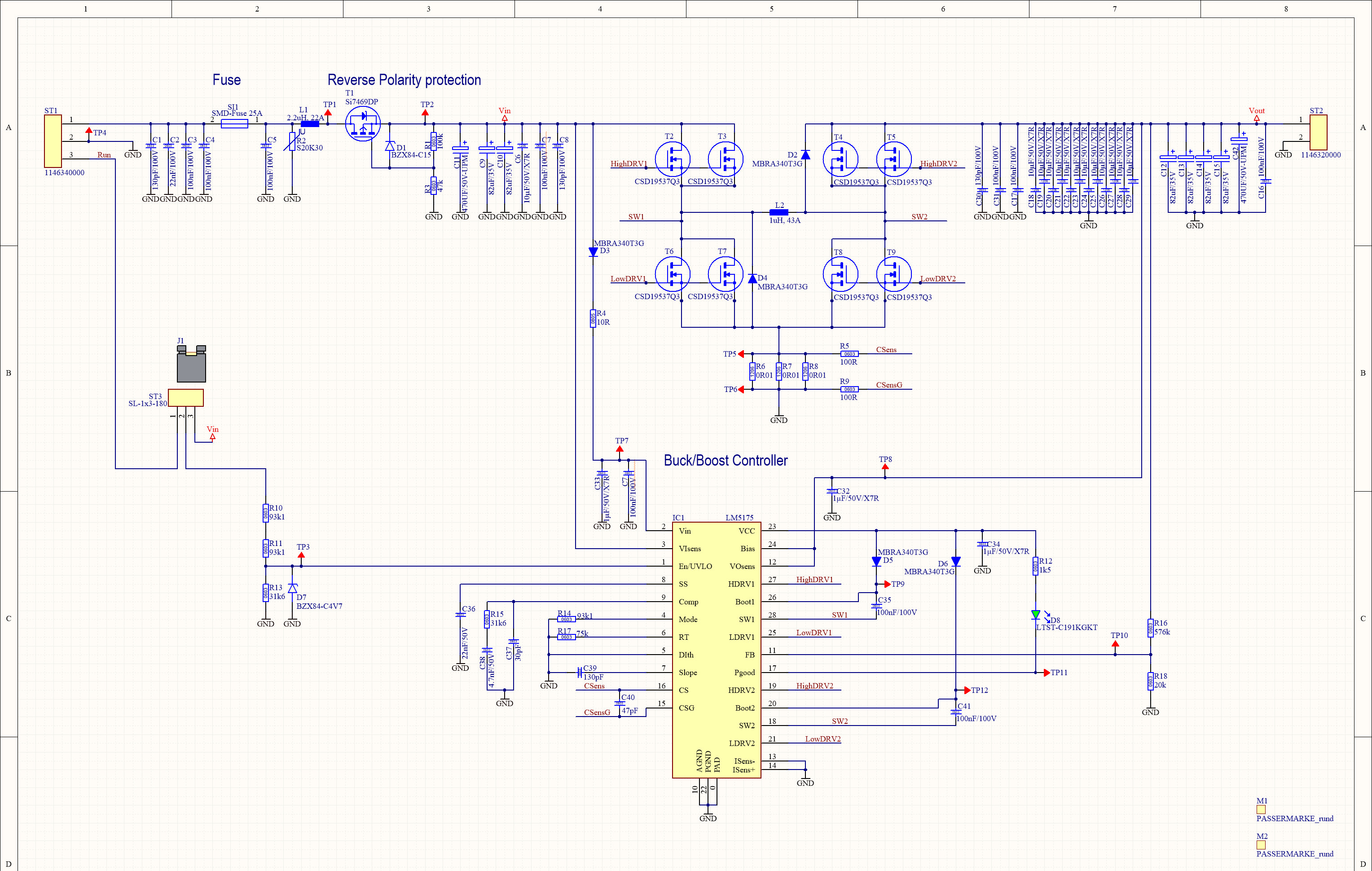
Schematic :
What I tried during the last days :
- Changed the boost capacitors to 220nF liek in the TI eval board -> no change
- Changed the VCCcapacitors to 4,7µF like in the TI eval board -> no change
- Doublechecked and replaced all resistors and capacitors at SS , Comp, Mode, RT and Slop -> all ok, same problem
- Changed to Compensation circuit to the values from the eval board -> same problem
- I scoped the four gate signals but at 12Vin they look good to me. High1 is on all the time, Low1 is off, High2 and Low2 switch inverted at 50% with a little delay at turnover.
- Removed the two diodes D2 and D4, just to be sure-> same problem
- Unsoldered one LM5175 to check for shorts under it, nothing found.
- Ordered some LM5176 and replaced the LM5175 in two pcbs, changed the frequency resistor accordingly : Same result with the LM5176, It also get's hot and inductor gets hot.
- unsoldered one of the two parallel transisors at high2 and Low2 to reduce gate capacity -> same problem
- Changed FB resistors to 270k/20k to get closer to the eval board. Output voltage changed to 11,6V but high current at no load stays.-> Same problem
I think I have no more ideas what to try next. Any help is appreciated !

