This thread has been locked.

If you have a related question, please click the "Ask a related question" button in the top right corner. The newly created question will be automatically linked to this question.

ISO5452: ISO5452

Part Number: ISO5452

Dear Audrey,

I have tested the IC - ISO5452 along with IGBT - SKM150GB12T4.

Following is the details as mentioned below:-

Vp = 15V.

Vn = -6.8V.

Rg = 1.2 ohm.

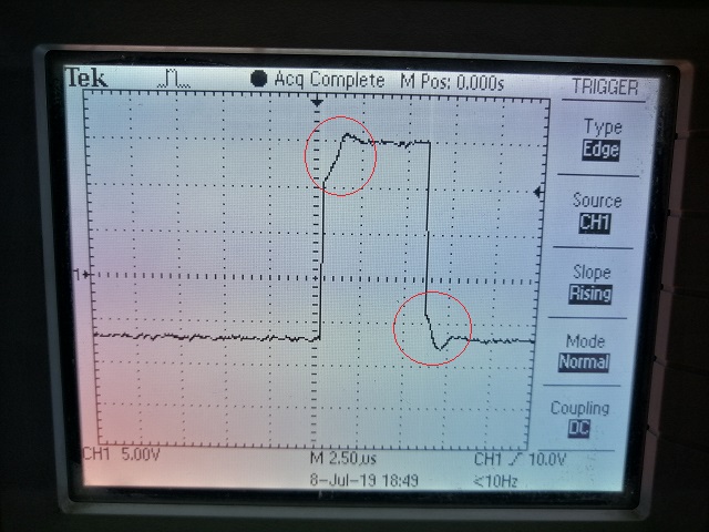
I have shown the image of Vge below:-

There is slight dip in gate emitter voltage at turn on and turn off which can be seen by red circles.

Kindly enlighten me on the same.

Thanks & Regards,

Vedang.

  • Hi Vedang,

    The dip could be due to the re-direction of the gate current due to the Miller effect. The Miller effect is the re-direction of current through the capacitor Cgc, which changes with Vce. You can verify this is the case if you also measure Vce and see that it is in transition during the dip in gate voltage. The gate current may be increased to reduce the time of the plateau if the IGBT is switching too slowly. You can reduce Rg lower than 1.2 ohms and see if it reduces the plateau. Otherwise, you may use an external npn/pnp BJT buffer to increase the current drive strength and increase the switching speed.

    Regards,

    Audrey

  • Dear Audrey,

    It means that if the current drive capacity of driver is not sufficient then such dip would be observed at turn on and turn off. The response become much more worse upon increase in gate resistor. I will try with BJT buffer at output.

    Thanks & Regards,

    Vedang