This thread has been locked.

If you have a related question, please click the "Ask a related question" button in the top right corner. The newly created question will be automatically linked to this question.

UC3846: test circuit

Part Number: UC3846

hello everyone ;

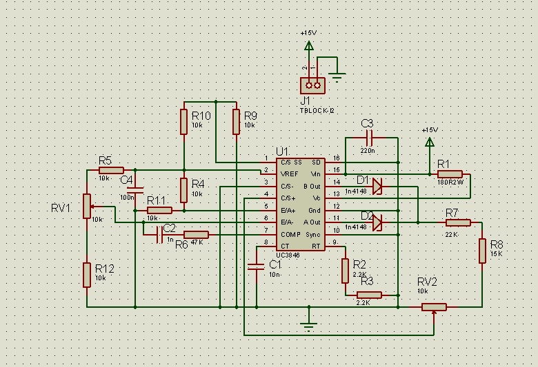
ı wanna design a converter with uc3846.But first tried to make a test circuit to see the output PWM signals.ı made all calculations and drawing .(ı will put them below) but ı can see anything.

ı couldnt understand whats wrong.can someone help me please?

Fswitching=2,2/4,4x0,01=50kHz

dead time =1,62uS

3xIsxRs=(R2xVref/(R1+R2)-0,5)====>Vsmax=IsxRs=1,06V

  • Hi Serkan, I will get back to you soon.——Teng

  • Hi Serkan,

    Sorry for the delay. Your test circuit seems good.

    Here is my suggestions.

    1. Try to add a RC circuit at CS pin to provide a ramp at CS+ pin.

    2. Ensure -E/A pin (Pin6) voltage is smaller than +E/A pin (Pin 5)  voltage, and COMP pin (Pin 7) has a voltage larger than 1.5V.

    If  it still doesn't work, please provide the voltage of  VREF pin, EA+ pin, EA- pin and COMP pin and provide the waveform of CT pin and CS+ pin. So that I can help you further.

    Regards,

    Teng 

  • Hi Serkan, I haven’t heard back from you, I’m assuming you were able to resolve your issue. If not, just post a reply below (or create a new thread if the thread has locked due to time-out) – thanks, Teng