This thread has been locked.

If you have a related question, please click the "Ask a related question" button in the top right corner. The newly created question will be automatically linked to this question.

LMR62014: Help with step trans/glitch on output

Part Number: LMR62014
Other Parts Discussed in Thread: TPS62745, , MSP430FR2476, ALLIGATOR

Hello,

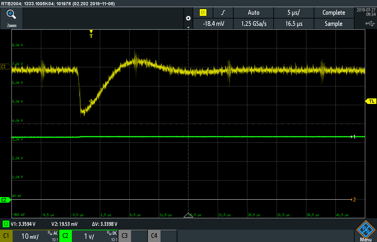
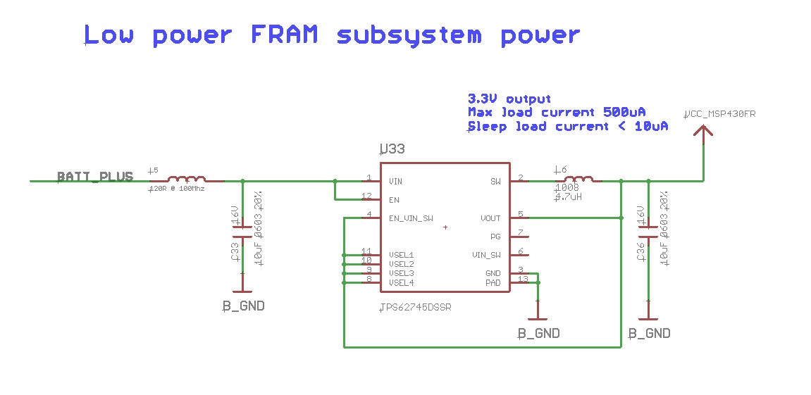
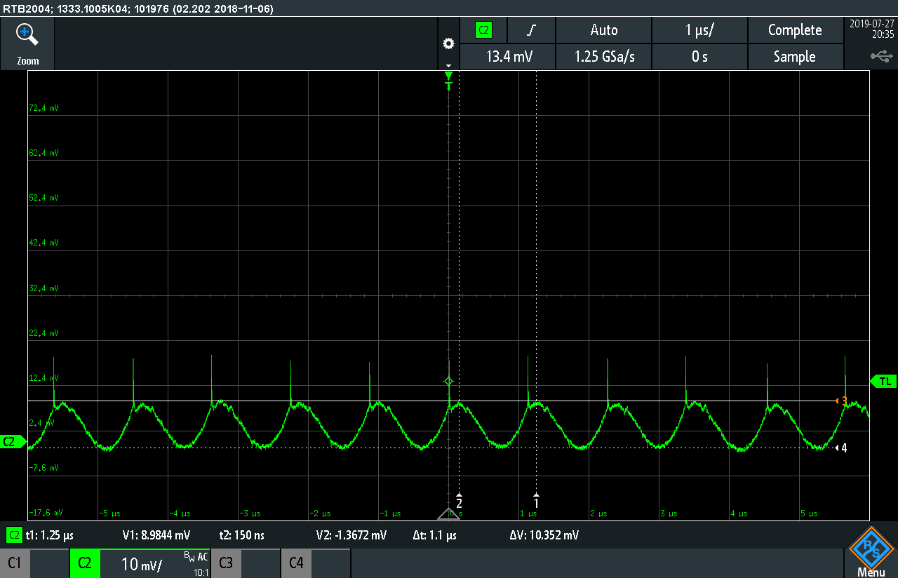
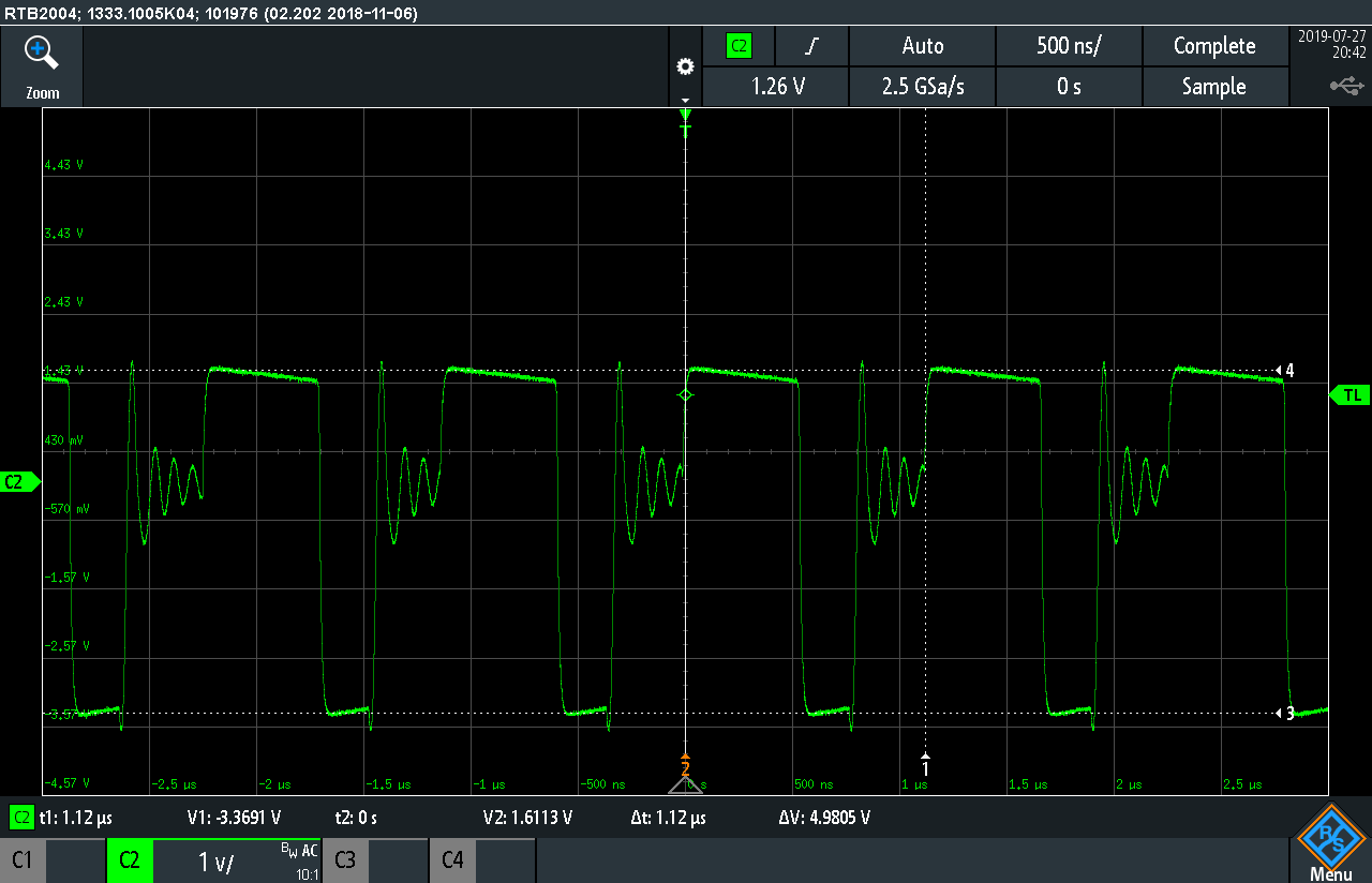
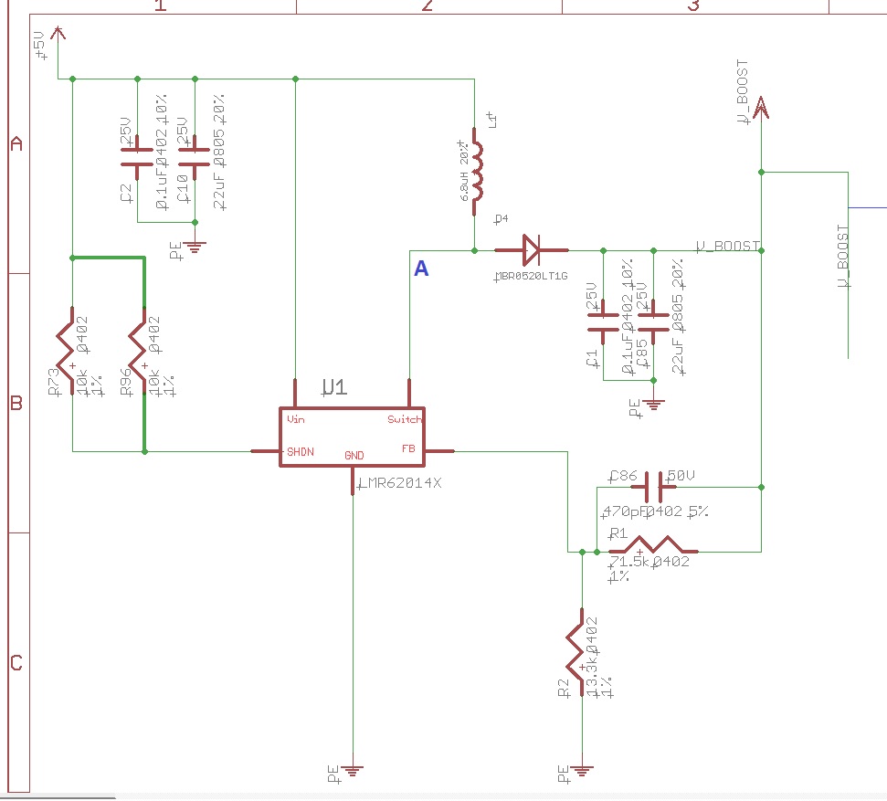
I have the LMR62014 designed in a product.  This part is boosting 5V up to 7.8V.  I then have a TPS62745 powered from this 7.8V.  There is a sharp transient that is coupling into the output of the TPS62745 because of a sharp transient dip on the output of my boost supply.  I can't figure out where this is coming from.  I have tested the 62014 with a 50mA load and without a load and this very short glitch/dip is always there.  I've attached a few screenshots and my schematic.  How should I go about eliminating this noise.  I think other than this the 62014 seems to work fine.  

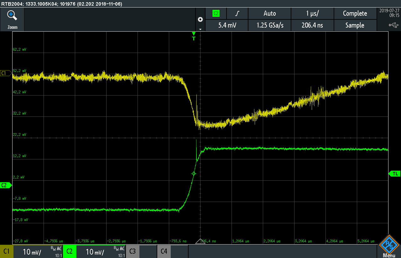
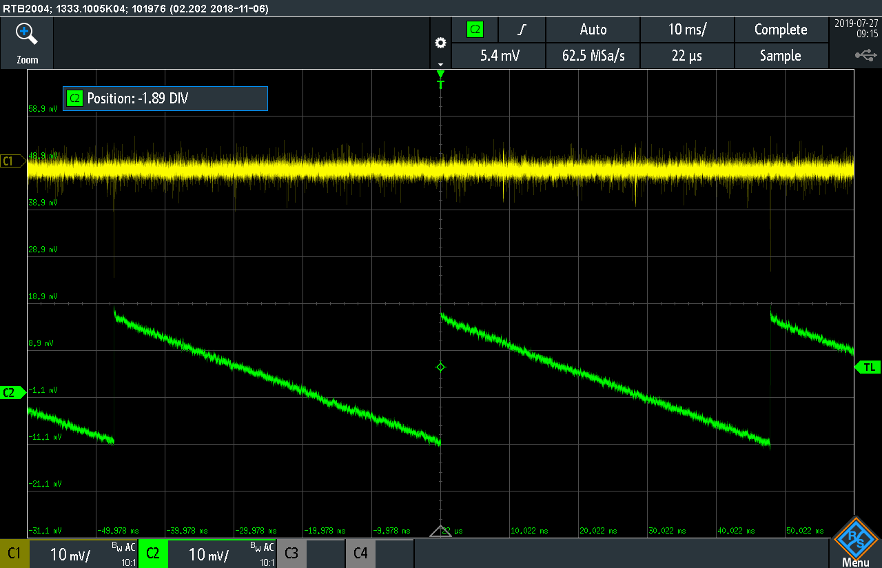
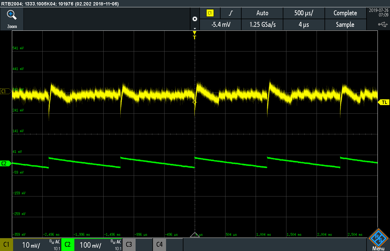
Screenshot 1: Ch1 = output of 62014 and ch2 (green) is output of TPS62745 which is powered by the 62014

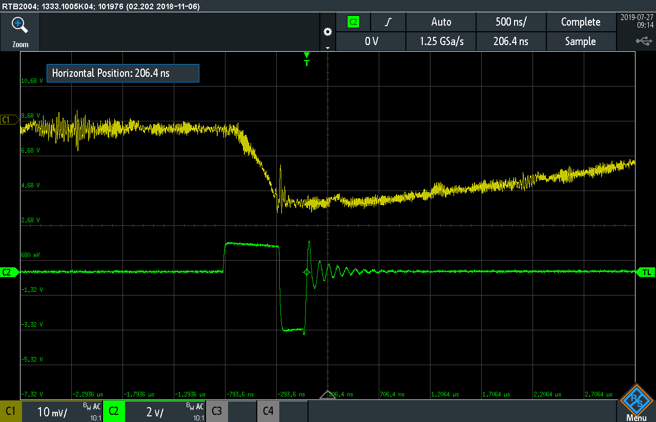
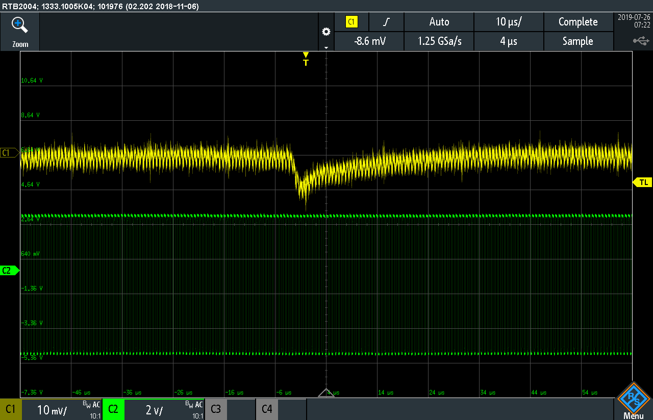
Screenshot 2: Ch1 = 62014 boost output, ch2= switch node shown as node A in the below schematic.

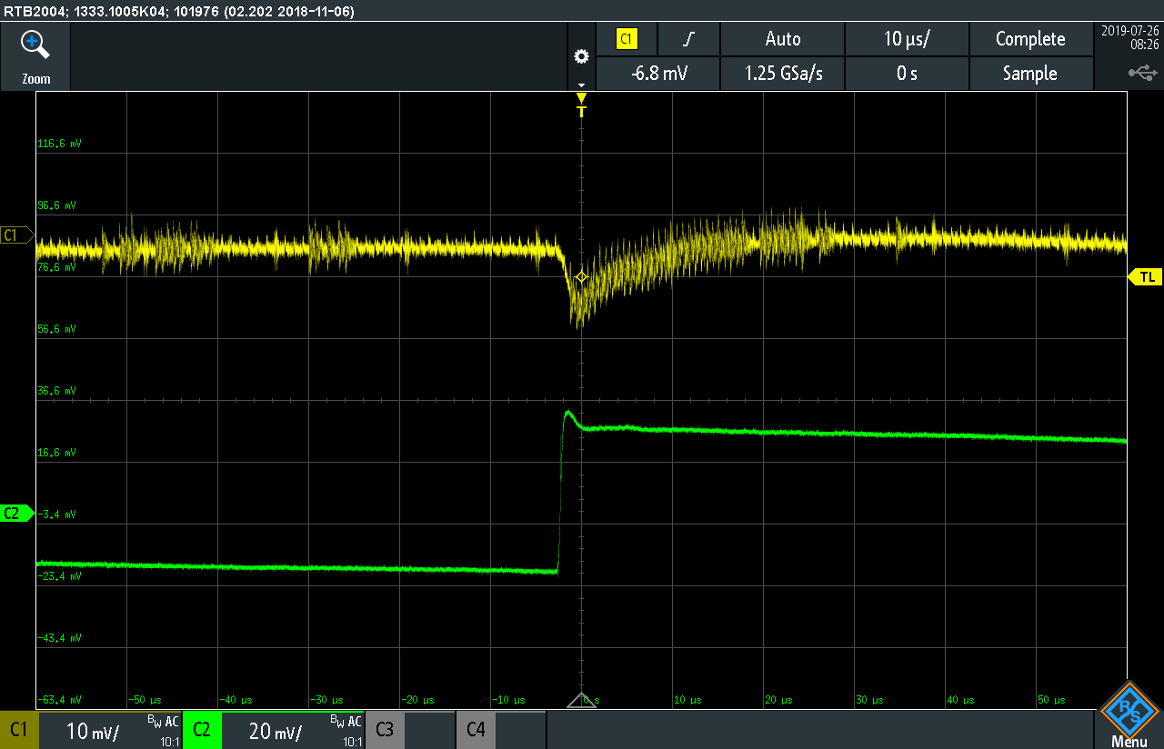
Screenshot 3: zoomed in version of screenshot 1.
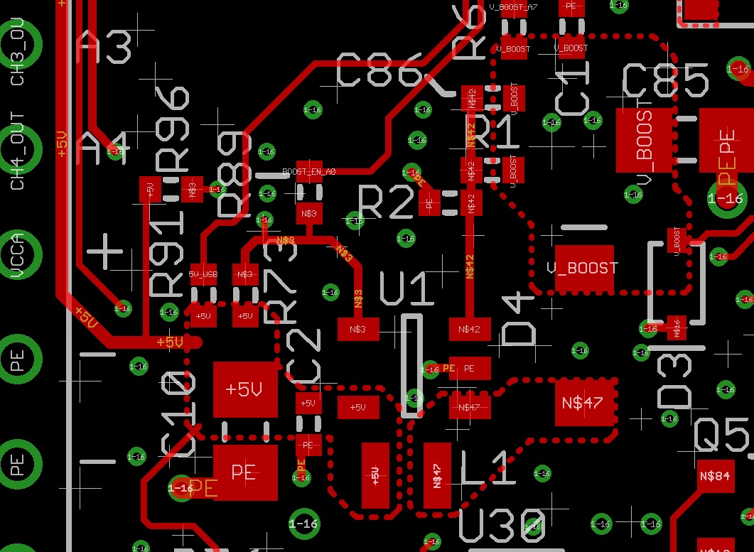
Schematic:

I built up a blank board by hand with ONLY the LMR62014 circuit and I still saw these high frequency dips on the output.  I'm a little unsure where to go from here.  Does anyone have any troubleshooting advice?

  • HI Robbie,

    Please follow the layout hints on page 10 in datasheet. You PCB layout needs a big improvement.

    What's the time scale of picture 2 and 3? Because you say picture 3 is the zoomed in of picture 2 but the time scale of two pictures are all 10us/div. I cannot understand. Is it vertical scale of CH1 10mV/div?

  • Hi Zack,

    I apologize I was incorrect.  Screenshot 3 is a zoomed in view of screenshot #1.  

    I"ve been testing tonight and believe I have found the issue.  The LMR62014 actually has been working fine when the TPS62745 is disconnected.  I think there is an issue with the TPS62745.  I say this because of the below screenshots and becuase I've verified that the LMR62014 is working fine without the TPS62745 connected.

    I've setup a new test where I've powered the TPS62745 by itself with a power supply.  So, I've isolated the TPS62745 and connected the input to a bench top supply with 5V and have probed around.  The only thing connected to the output of the TPS62745 is an MSP430FR2476 which is in its default state it has not been programmed or touched after these boards came in.  I've verified that when the board is powered off there is about 16.5k of resistance from the output of the TPS62745 to ground.

    Screenshot #N2-1: This is a screenshot of the input which is yellow (Ch1) and the output (green - ch2).  Ch1 is the input from a bench top lab supply outputting 5V and ch2 is the switch node of the TPS6245.

    Screenshot #N2-2: This screenshot shows the same test setup as screenshot N2-1 but channel 2 (green) is probing the output of the TPS62745.  This shows a comparison of the input and output.  

    Screenshot #N2-3: This screenshot shows the same test setup as screenshot N2-2 but I've zoomed out on the scope to show the large slow sawtooth wave seen at the output of the TPS62745.  

    The scope is set to use AC coupling for both channels in all of these screenshots.  It looks like from screenshot N2-1 that when the switch turns on it creates a step load on the input that is very short in duration, but noticeable in magnitude.  I thought this was due to the boost converter last night because that feeds the TPS62745, but this seems to show that when the TPS62745 switch turns on it creates a fairly large step causing the input to glitch even when on a robust lab supply.  

    When the board is powered off I measure 16.5k ohms between the output of the TPS62745 and ground.  I initially thought the output might be overloaded or shorted.  This doesn't seem to be the case either.  The TPS also seems to be regulating around 3.3V as shown below.

    Screenshot #N2-4: Ch1 (yellow) is TPS62745 input and Ch2 (green) is TPS62745 output with cursers and DC coupled.  This shows the dc regulation point is in fact around 3.3V

    The schematic for the TPS62745 is shown below:

    EN_VIN_SW should be tied to ground, but I verified with a different post here that it wouldn't cause an operational issue.  

    I feel like something has to be wrong - I would expect these supplies to be quieter than 30mV ripple as shown in screenshot #N2-3.

  • Today I tested the TPS62745 with a 100mA load on the output using a BK precision active load (model 8601).  The active load was set to 100mA constant current.  The output waveform changed to the one shown below.  It still seems awfully noisey.  The output was measured with a rhode and scwartz RTB2004 with a 10x probe.  I used the small spring lead for ground (short ground lead) rather than the clip on alligator ground wire that is ~6 inches long.  

    The wave form at the switch node for the same setup and load is shown below.

  • Hi Robbie,

    Sorry I only support LMR62014. For TPS62745, please send a new post on E2E with only TPS62745 tag to get help from our Buck expert. 

    I'll close this thread now.