This thread has been locked.

If you have a related question, please click the "Ask a related question" button in the top right corner. The newly created question will be automatically linked to this question.

LM9076: Datasheet Question

Part Number: LM9076
Other Parts Discussed in Thread: TPS7A05, TPS7A16

In the LM9076 Datasheet on page 10, "OUTPUT CAPACITOR" section, the first paragraph says the following:

An output bypass capacitor is required for stability. This capacitance must be placed between the LM9076 VOUTpin and Ground pin, as close as is physically possible, using traces that are not part of the load current path.

QUESTION: How can you avoid using the Vout trace, through which "load current" flows?  Vout is the "load current path."  For that reason, I don't understand the meaning of the text above.  Do you have an example PCB or can you otherwise explain "traces other than the load current path"? 

Thank you.

  • Hi James,

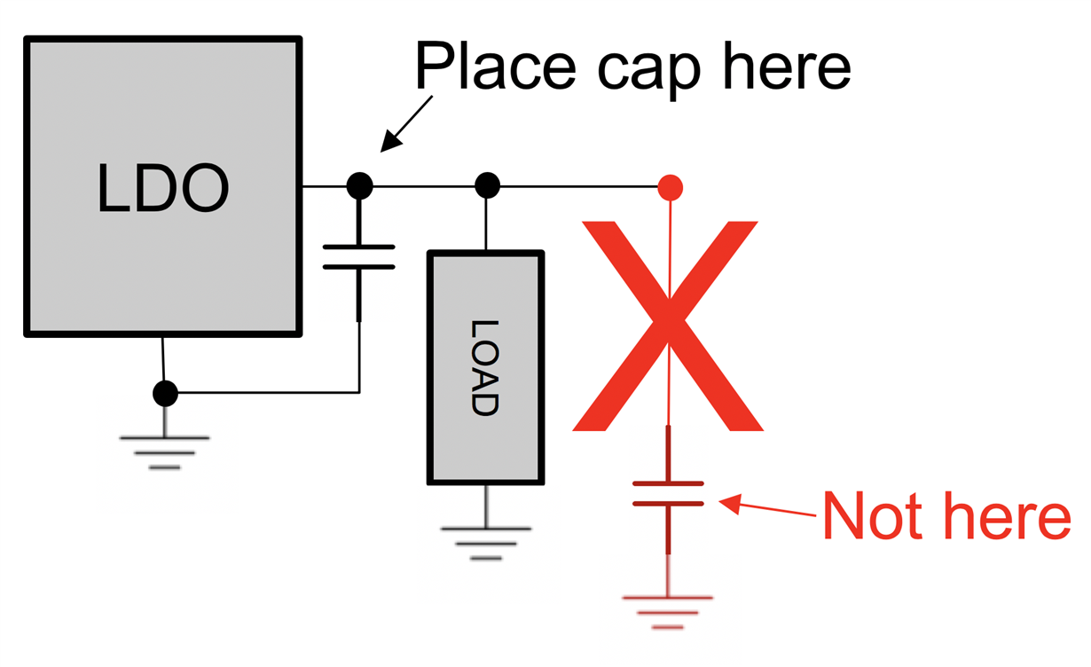
    Here is an example of what the datasheet is recommending to avoid:

    Does this answer your question?

    Regards,

  • Thank you for the reply.

    Of course, schematics do not speak anything about PCB trace width, length, thickness, or resistance.  Schematics speak only of the electrical connections, which means if you place your schematic's red line/cap/gnd on the left or right of the load, it is 100% electrically the same and therefore doesn't matter one bit.  But I will infer that you mean something similar should be done on the PCB side.  Even so, you spoke nothing of TRACE LENGTH.  

    Technically speaking, if I put your red line/cap/gnd 1mm to the left or right of the load, it won't make much difference at all.  So again I must infer that the 22uF capacitor (the cap you colored red in your schematic) should be placed right up against the LDO IC, as close as possible, and then there should also be some rather substantial PCB trace length that leads away from the positive side of that 22uF cap to the load, correct?  But again, how long of a trace will depend on trace width and thickness, and that's a real mystery to me.  Consider well the "INPUT CAPACITOR" section on that same page in the datasheet very clearly says the input cap should be placed "within two inches of the LM9076" and is why I am rather confounded what such detail is not given with regard to physical placement of the OUTPUT CAPACITOR.

     Furthermore, I would still argue that the following statement in the datasheet is high confusing at best:

    "...using traces that are NOT part of the load current path."

    Technically speaking, even in your suggestion of moving the load path further from the 22uF capacitor, that PATH is still the SAME PATH!  Right?  Or am I way off base here?

  • HI James,

    I agree these older datasheets have some confusing or unclear statements. This is an example of one of them.

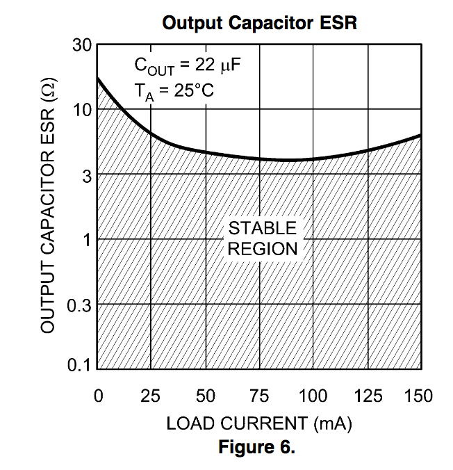
    I am sorry I was not clear in my example above, but the intent was to show physical placement as an example of "...using traces that are NOT part of the load current path.". This recommendation is here as this LDO has a a very specific range of output capacitance and ESR that it is stable with. By placing the capacitor as close as possible to the LDO limits the possibility of parasitic impedance in the trace from adding too much effective ESR. This graph from the datasheet shows the allowable ESR when using a 22uF capacitor:

    To answer your question above, yes the 22uF capacitor should be as close as your layout allows to the LDO. The capacitor should also have less than 3Ohms of ESR to ensure stability.

    With respect to the input capacitor. That too needs to be close as possible the datasheet states that the internal bias circuitry uses this. This is primarily to minimize droop on VIn if there is inrush into the load or a fast load transient event.

    Our modern LDO's like the TPS7A05 are much less sensitive to ESR and can be used with any capacitor and even much smaller values. The TPS7A05 is an example of our latest and greatest LDO that might be easier to use.

    I hope this answers your question. If not, let me know.

  • Thank you for the information, John.  Below is a schematic of my circuit which is intended to be used in both 12V and 24V vehicles, which is why I cannot use the TPS7A05.  The LM9076BMA accepts a rather high Vin, which is required in my automotive application.  The LM9076 datasheet says "55V absolute max" for Vin, so I am quite curious why only 40V is specified.  Here too I must make an assumption that voltages from 41 to 55V are allowed, but only for a short duration, albeit perhaps a longer duration than the 10ms (1% duty) allowed for surges of up to 70V.  But anything in the 50V range and higher would be a transient/surge in my application, so I picked a TVS that caps the surge to 53.9V, which is under the Vin-max of 55V and I assume should be fine, especially since the 1N4004 (for reverse polarity protection) will drop the voltage yet another 1V.  (I could pick a TVS with lower Vc, but the TVS I chose allows higher voltage to pass before TVS breakdown, which is important in 24V truck applications.)

    You're right about the LM9076 being extremely sensitive about capacitor ESR.  And that is why I am curious how my 22uF 0.9-ohm Tantalum output capacitor will be affected by the 0.1uF ceramic caps I intended to scatter throughout my circuit on the 3.3V rail.  Obviously, there will be trace length and trace resistance here, but how long the traces need to be to avoid "resistors in parallel" affects on the 22uF cap is something I need to ponder.  Because obviously a 0.9-ohm cap in parallel with a 0.008-ohm cap yields 0.0079-ohm!  And the datasheet graph indicates the ESR should be above 0.1-ohm.

    Anyway, since the datasheet specifies a minimum Vin "ceramic" capacitor of 1uF, as you can see in my schematic below, I choose 0.22uF for safety, which is in addition to my 660uF of combined aluminum electrolytic input capacitance, which I added to maintain Vin during vehicle cranking.  This LM9076 LDO will drive my 3.3V MCU and other circuitry which could draw as much as 100mA, so 150mA gives me some safety headroom.  And while I know a switcher could be used here, the LM9076 should give me lower quiescent current than a switcher, especially since the standby current draw of my circuit will be less than 2mA (average).

    In light of this, if you have a better voltage regulator recommendation, I am happy to consider it.  But as far as LDO regulators go, it seems the LM9076 is especially suited to my application.  I just wanted to clarify the datasheet so I don't make any implementation mistakes in my application.

  • Hi James,

    It would take a bit of research to find out why the datasheet has an abs max of 55V but recommended up to only 40V. The all TI datasheets do not guarantee performance outside the recommended operating range.So in your case, I think there is no issue.

    I am not sure if you have seen the TPS7A16. This has both automotive and non-automotive versions. This is a 60V abs max, 5uA Iq, 100mA LDO with Power good, and delay. So similar functionality to the LM9076 but with improved functionality. We designed this specifically to be able to handle cold crank and load dump. You would still need D2 for reverse current protection, but your capacitor requirements are much less strict.

    Let me know what you think.

    Regards,

  • John,

    I certainly appreciate your kind analysis of my application and suggestion of the TPS7A16.  It looks well suited for my application, except for the 100mA output current specification.  Some of my onboard circuitry will draw just about 100mA, and that is why I ultimately selected the LM9076 due to its 150mA output.  The extra 50mA of current output headroom makes me feel more comfortable.  I do have one question about the TPS7A16 datasheet regarding output current. On page 11 in section 7.3.5 it says the following:

    The maximum amount of current the device can source is the current limit (225 mA, typical), and is largely independent of output voltage.

    I assume that sentence means I could output more than 100mA for short periods of time using the TPS7A16?  

    My circuit may require roughly 100mA continuously for periods of 30 seconds.  So if the TPS7A16 can accommodate that easily, then it might be a reasonably good choice.  However, the datasheet does recommend 10uF ceramics on the Input and Output, as per section 8.2.1.2.1.3, which are rather expensive at higher voltages (i.e., I would need to use a 63V 10uF ceramic for Vin, which depending on volume can cost as much as the TPS7A16 chip.)   

    Assuming my use of 0.1uF ceramic decoupling capacitors on the 3.3V output rail (e.g., MCU Vcc pin, etc.) of the LM9076 won't reduce the effective ESR so low the 9076 becomes unstable, I think the 9076 may still be a reasonably good choice for my application.  So if you have specific thoughts about that, I believe that would be my final question in this discussion.  

    Thank you!

  • HI James,

    The TPS7A16 is design to support a nominal 100mA of current. This assumes the design thermally can handle this. Meaning (24V-3.3)*0.1 is dissipating 2.07W. Using TJA of 44.5C/W (SON package on a High-K board), this results in a die temperature that is ~92C above ambient.  Please have a look at SLVAE85 which is a recent application note on thermals for more details

    The minimum current limit threshold on the datasheet is 101mA, and I looked at the actual characterization data  has a minimum measured current limit of ~180mA. So I think your 100mA nominal load is safe. Sourcing brief transients up to 225mA should be OK assuming these are very short transients as the current limit does take a few micro-seconds to engage. Adding some additional bulk capacitance at COUT can help ride this out.

    With respect tot he capacitor recommendations. The output capacitors are for stability. The input recommendation is made assuming ceramics are preferred. If you would like to use Aluminum Electrolytic or any other dielectric (except Y5V which is not recommended) that is more cost effective, that is OK.

    Now with respect to your last question; Adding a 0.1uF ceramic in parallel with COUT may impact stability of the LM9076. Even if your lab tests and per-production builds look OK, lot to lot variations might result in a performance issue in the future. If the TPS7A16 can work for you, this might be the more reliable solution.

    I hope this helps.

    Regards,

  • Thank you, John!

  • You're welcome!