Other Parts Discussed in Thread: LMR36015, LMR36006
Hi,
Customer measurement chip temperature using FLUKE thermal camera, they found LMR36015-Q1 surface is hot then PCB board 20°C Below is customer provide info.
- Ambient Temperature : 25°C
- Board Temperature : 45°C
- LMR36015 Temperature : 65°C
- Pin : 24V * 37mA : 0.89W
- Pout : 3.3 * 230mA : 0.759W
- PLOSS : 0.89 – 0.759 : 0.13W
Question1: LMR36015-Q1 current rating is 1.5A but customer board output current just 230mA, why the chip surface temperature higher then board 20°C.
On customer board LMR36015 is the most hot chip, the other chip didn’t have significant temperature increase.Using below formula to roughly calculate heat increase the LMR36015 should not so hot.
TJ = ΨJB * PLOSS + TB = 23.5 * 0.178 + 45°C = 49 °C
Question2: If above formula is not right ,please help to answer how to roughly calculate the TT and TJ. Should I using ψJB or θJA

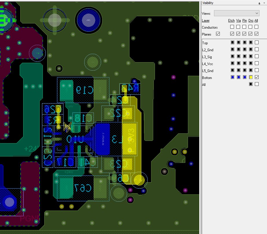
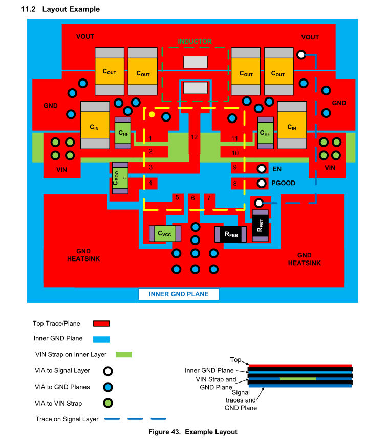
Question3:This chip do not have thermal pad, and on the d/s layout guide the PCB heat sink is put in PIN6(AGND), customer think the pad is so small . Is it effect improve the thermal resistor?
Why choosing PIN6 to transfer heat not PGND or other pin? Below picture is customer’s schematic and layout, they do not follow the layout guide pour ground plane on Pin6. Whther or not this cause the heat increase?


Thanks