This thread has been locked.

If you have a related question, please click the "Ask a related question" button in the top right corner. The newly created question will be automatically linked to this question.

BQ29700EVM-610: bq29700

Part Number: BQ29700EVM-610
Other Parts Discussed in Thread: BQ27000, BQ2970

Hi Sir,

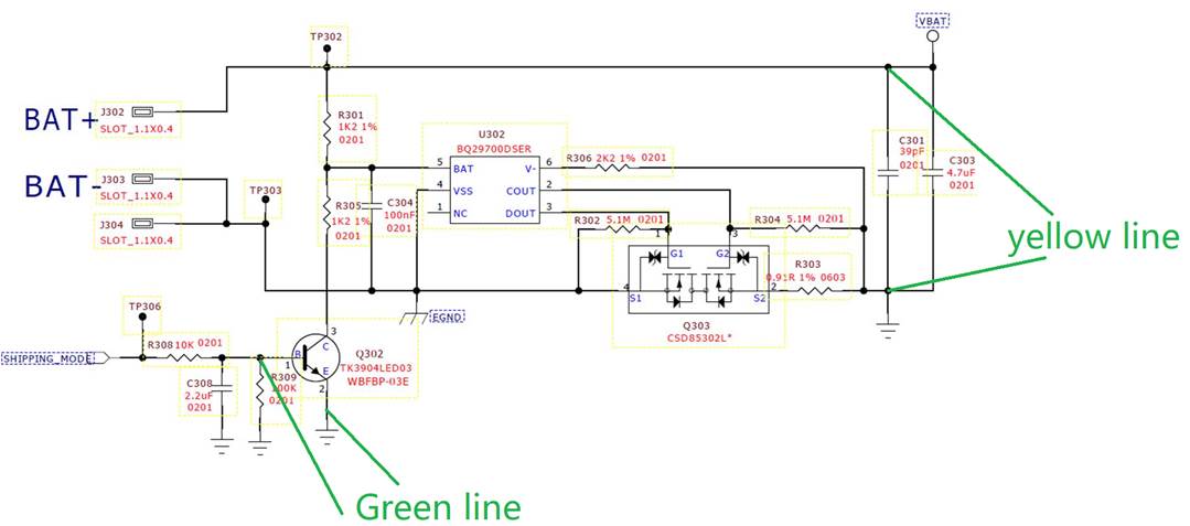
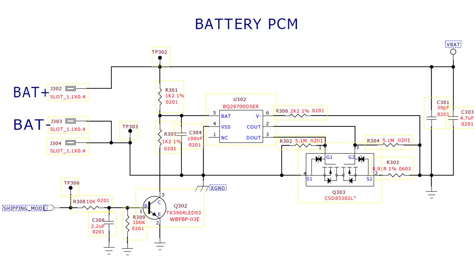
Below is my customer circuit design for the BQ27000. The idea is to simulate a Under-voltage protection to activate the PCM cut-off when we enable the Q302 transistor to enter shipping mode.

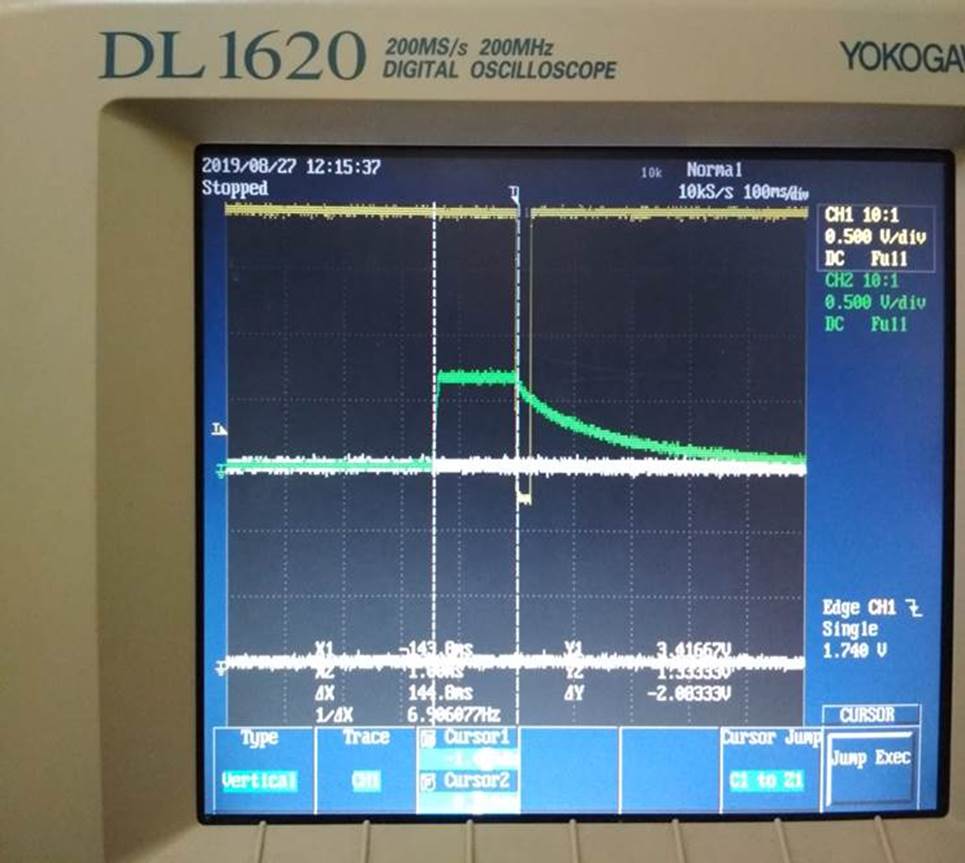
Currently we are seeing some units where the battery levels go down and come up after 20ms after the entering the shipping mode. The bounce up did not happened in good unit.

Could you please help advise what could be the possible reason for this from the PCM IC point of view? We can see that the PCM starts to kick-in to cut off the VBAT power but somehow it exits this scenario and we did not apply the charger to the unit during the process.

Yellow Line Indicates Battery

Green line indicates Q302, which is controlled by PIO19 shipping mode pin from the microcontroller.

 1. Shipping Mode - Problematic Unit

2. Shipping Mode - Working Unit

Thanks, Ian.

  • Hi Ian,

    To better understand this situation, I need the answers to these questions:

    1. Where on the circuit are you probing the signal and ground in these scope shots?
    2. What are the other signals (in white) on the scope shots?
    3. Does the microcontroller remain on throughout this process?
    4. Is this issue repeatable on the same units? Can you get the same units to consistently fail or pass, or is it random?
    5. What is the failure rate? Is it most of the units that are not behaving as desired, or just some?
    6. The behavior of this device in UVP is determined by the values of the BAT and VSS pins. Can you determine the values of those pins in each of these fault modes? This may help identify the issue. 

  • Hi Shawn,

    Hare are answer as below,

    1. Where on the circuit are you probing the signal and ground in these scope shots?

    A:  please refer to diagram below

    2. What are the other signals (in white) on the scope shots?

    A: please ignore the white line, it’s not connected to anything.

    3. Does the microcontroller remain on throughout this process?

    A:  Yes, the microcontroller is still ON and will wait for the PCM to cut off the battery supply to the microcontroller.

    4. Is this issue repeatable on the same units? Can you get the same units to consistently fail or pass, or is it random?

    A: Yes, it is repeatable on the problematic unit.

     5. What is the failure rate? Is it most of the units that are not behaving as desired, or just some?

    A:We are seeing 10-20% failure rate.

     6. The behavior of this device in UVP is determined by the values of the BAT and VSS pins. Can you determine the values of those pins in each of these fault modes? This may help identify the issue.

    A:  The units assembled will have battery voltages around 3.7V ~ 4.1V.

    Thanks,Ian.

  • Hi Ian,

    Thanks for answering those questions for me! I have a couple things I want you to try, hopefully they will help you with your issue.

    First, could you try letting your batteries generate the UVP fault? I want to make sure that the circuit still behaves normally. 

    Second, could you try enabling the transistor for a longer period? 20ms is not long enough to trigger a UVP.

    Lastly, can you make sure that no other faults are occurring when you have the correct behavior? It could be that some sort of current protection is triggering and not the UVP.

  • Hi Ian,

    I haven't heard from you in a while, do you have any additional questions?

  • Hi Shawn,

    We are able to trigger the UVP at 2.8V so the circuit is working fine.

    From the scope capture, we can see that the UVP trigger time is 144ms or more which is what is mentioned in the spec.

    We also been monitoring the current draw from battery but it is definitely much lesser than 15mA so it should not be a current protection case.

    I would like t know once the UVP is triggered, what could have cause the PCM to be re-enabled again (meaning the BAT- connects back to digital GND)? What VBAT voltage point would have triggered the PCM to be activated again?

    Thanks, Ian.

  • Hi Ian,

    In order to recover from a UVP fault, refer to section 9.4.3 of the BQ2970 datasheet. This section states that the device will recover if the charger is connected and

    • The battery voltage exceeds Vuvp (if V- is lower than -0.7V)

    OR

    • The battery voltage exceeds Vuvp + hysteresis (if V- is higher than -0.7V)
  • Hi Sir,

    Since we do not have the charger plugged in, what could have caused of the recovery from UVP fault?

    Thanks, Ian.

  • Hi Ian,

    If the battery voltage exceeds Vuvp, the device might think a charger is connected and recover. In order to keep it in fault mode, the battery voltage must stay low. 

  • Hi Shawn,

    From the scope graph that provided, you can see that the battery voltage is falling and for some reason the system voltage turned back on.

    From the schematic, you can see that the Q302 is holding the voltage sense pin 5 of U302 low.

    As the MCU is holding the pin low of Q302, the pin 5 of U302 will be low as long as Q302 is on.

    Is the any criteria if the pin5 must continue to be held low AFTER the vbat cut-off to the system has been activated?

    So if U302 starts cutting off the power to the system, we expect that it will continue to cut off as long as there is no other change to the system input eg, no charger inserted.

    Note that as the battery voltage cuts off, the mcu control to the Q302 will eventually release.

    So it becomes critical for us to know how long the pin5 must remain low so that the U302 will continue the cut-off of the VBAT power.

    Thanks, Ian.

  • Hi Ian,

    In order for the device to stay in the fault mode, the voltage on pin 5 must be continuously held low. If the voltage rises up for longer than 144ms, the device will recover. If the battery voltage still remains over the UVP limit, it will recover even if there is no charger connected. 

    For your application, I think the MCU would need to pull that pin low until you are ready to remove the device from shipping mode. 

  • Hi Shawn,

    Thanks for the update. The MCU will eventually lose power as VBat is being turned off. The question is how long should pin5 remain low?

    From my understanding, if pin 5 is low for 144ms, then UVP is triggered. As can be seen from the graphs sent to you earlier, the UVP is triggered. The question is AFTER the trigger, we do not expect the VBat to turn back on. Under what condition will it turn back on AFTER UVP is triggered assuming no charger is connected and only Q302 controls the low voltage to the pin5. Do you mean that the chipset U302 will require the pin5 to be kept low AFTER UVP is triggered and if so for how long should it be held low AFTER UVP is triggered?

    Thanks, Ian.

  • Hi Ian,

    Yes you are correct. Once the BAT pin is pulled low for 144ms, UVP will be triggered. If you release the pin and allow it go high again, the battery will reconnect. From my understanding, the battery is still above the UVP threshold. Once the battery is reconnected, the voltage on the BAT pin will rise above the UVP threshold and the device will go back into normal operation, there is no delay. Since the UVP fault was simulated by the Q302, a charger is not required for recovery.

    If you would like the chip to stay in fault mode, the voltage on pin 5 cannot exceed 2.8V after UVP is triggered. It must stay low until you are ready to resume normal device operation.