This thread has been locked.

If you have a related question, please click the "Ask a related question" button in the top right corner. The newly created question will be automatically linked to this question.

LM2665: LM2665 output

Part Number: LM2665

Dear Team:
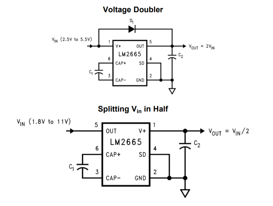
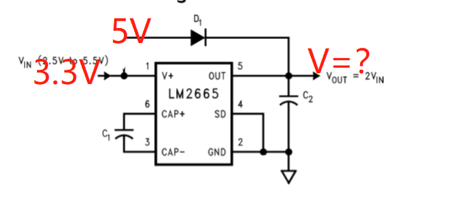
     My customer want to used LM2665 turn 3.3V to 8V, and the design as below, is this circuit correct?

     What does D1 do?

   Thanks!

Regards!

Eric Shen

  • Hi Eric,

    Thanks for reaching out with your question and using the LM2665.

    The LM2665 will double the input voltage, so for 3.3V input the output voltage would be 6.6V. Note the output is not regulated. If the input voltage changes so will the output voltage. The circuit above is not recommended at the the V+ pin needs to be connected to diode.

    What is the current of your application? A boost converter might be a good option for this application.

    Thanks,

    Garrett

  • Hi Garrett:

       Thanks!

       I need to ask you again, the two figures below, one has D1 and another has no D1,there have a big difference in the output, what is the function of D1?


  • Hello Eric,

    D1 either configures the LM2665 as a charge pump (increase the output voltage) or to decrease the output voltage from the input voltage.

    Thanks,

    Garrett

  • The datasheet says:

    9.2.1.2.1 Positive Voltage Doubler

    […]
    The Schottky diode D1 is only needed for start-up. The internal oscillator circuit uses the OUT pin and the GND pin. Voltage across OUT and GND must be larger than 1.8 V to insure the operation of the oscillator. During start-up, D1 is used to charge up the voltage at the OUT pin to start the oscillator; also, it protects the device from turning-on its own parasitic diode and potentially latching-up.

    9.2.2 Splitting V+ In Half

    […]
    In the voltage divider, the input voltage applies across the OUT pin and the GND pin (which are the power rails for the internal oscillator), therefore no start-up diode is needed.