This thread has been locked.

If you have a related question, please click the "Ask a related question" button in the top right corner. The newly created question will be automatically linked to this question.

TPS61236P: Audible noises in both custom PCB and in Evaluation Board

Part Number: TPS61236P
Other Parts Discussed in Thread: TPS61253A, TPS61022, BQ24073

Hello,

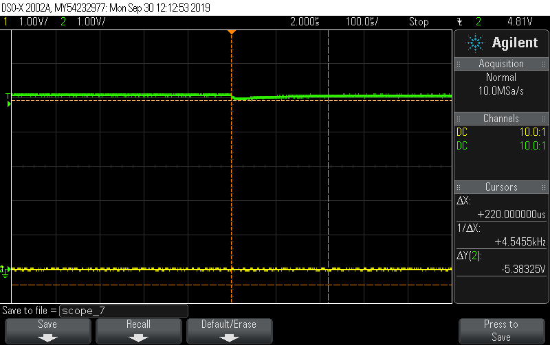
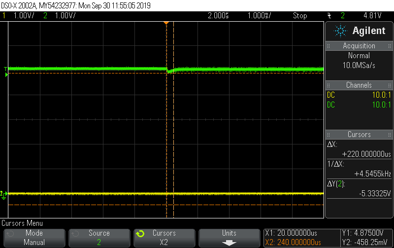
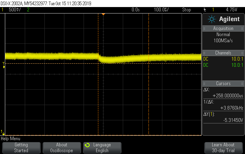
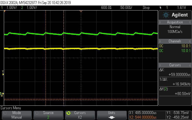
I read the related post https://e2e.ti.com/support/power-management/f/196/t/757404 and I too have this issue with audible noise. I measured the voltage at the input and the output of the boost and saw ripple at around 16-19 KHz under light loads (approximately 30-60mA). Below graph yellow is Vin and green is Vout. Vin and Vout are with respect to the TPS61236P labels.


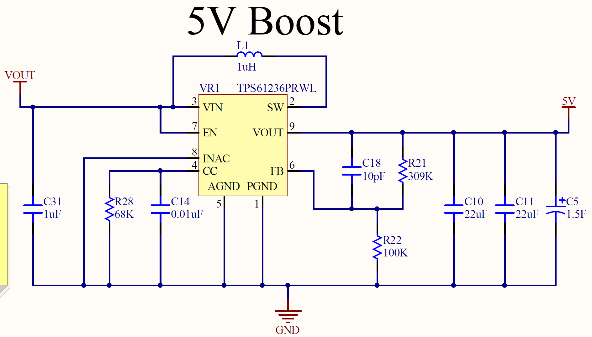
Here is my schematic as well. 

I know under light loads, the boost should enter the PFM mode. The waveform on Vout matches that given in Figure 20 of the datasheet (i cannot make out the time division info on the plot). Is it normal for this boost to operate in the audible frequency range (20Hz to 20KHz)? Are there modifications I can make to avoid this range or to at least reduce the noise?

Notes:

1. I have tested with the 1.5F capacitor off and on the board.

2. I have added extra capacity (150uF) MLCC on the input. 

3. The tantalum on the evaluation board does not change the audible noises.

4. The board makes a much louder noise during initial boot up with the 1.5F capacitor. (In this state, the super capacitor pulls Vout lower than Vin which turns off the boost. When Vin is lower than Vout it starts again. This continues until the capacitor is charged)

Here is a picture of the board layout

  • HI Tyler,

    the switching frequency could be within the audible noise frequency range at light load. the noise normally generate from the ceramic capacitor, and it also relate to the placement of the ceramic capacitor in the PCB. there is no very good solution. following are my suggestions:

    1. replace the large package ceramic with tantalum capacitor. (but still need small package ceramic capacitor for switching frequency noise)

    2. use a device with forced PWM mode, such as TPS61253A, TPS61022.

    What is the input and output condition for your project?

  • Hello,

    The input conditions are a voltage range between 2.8V and 4.4V. The output condition is 5V with a max current draw of 2A with a steady draw of up to 1.5A (USB charging).

    Would putting low acoustic noise capacitors such as the ones found below help reduce noise?

     https://www.digikey.com/products/en/capacitors/ceramic-capacitors/60?k=&pkeyword=&sv=0&pv405=2208&sf=1&FV=ffe0003c&quantity=&ColumnSort=0&page=1&pageSize=25

  • Hi Tyler,

    yes, i think the kind of capacitor should help. at least we can try this if the cost is acceptable.

  • Hello Jasper,

    Thanks for the response. We will try replacing the larger package caps with these acoustic dampening ones. It may be a while (a month or 2) until we can test these capacitors. I'll share our findings on this thread when we do get to testing. Please leave this thread open.

    Thanks,

    Tyler

  • Hi Tyler,

    sorry but I can't leave the thread open for one month or 2. as we have the requirement to close the post within a period.

    you can still reply after I close the post. if  the post is lock, it is easy to ask a related question, we will respond quickly to support.

  • Hey Jasper,

    We did some further testing on this issue and found the audible noise was composed of a steady hum and a variable frequency noise.

    It appears that we were seeing fairly frequent and large voltage spikes at our FB pin. We increased our 10pF cap (C18) to 150pF (GRM1885C1H151JA01D). This removed the spikes and we no longer hear this variable frequency noise. We had tried an 82 pF (GRM1885C1H680JA01D), but were still experiencing audible sounds and seeing small spikes still on FB. Is there any issue with using a 150pF capacitor with regards to phase margin or reliability?

    In addition, we were able to order in some of the low noise capacitors (ZRB15XR60J106ME12D and ZRB186R60J226ME11L). We took one of our custom PCB boards and replaced the two 22uF and the one 10uF capacitor around the boost. As well, we replaced 4 other 22uF capacitors that are near our battery connector and BQ24073 power chip. We found this reduced the steady hum noise significantly. 

    We also ran wires from our board to the evaluation board of the TPS61236. We found the low hum was completely gone. We then replaced the larger Inductor package (8 x 8mm) on the board with the smaller package size (4 x 4mm). When using the smaller package, we did notice there was a hum similar to our custom pcb with the noise reducing capacitors on. So it seems to get the quietest boost configuration, the larger 8mm inductor should be used. (We did remove the tantalum on the evaluation board and found there was no difference in audible noise)

    Tyler 

  • One last test,

    Replacing the normal 805 package 22uF with normal 603 package 22uF did not reduce the noise level significantly.

    Tyler 

  • Hi Tyler,

    thanks for the experiments and updates.

    as there is very large capacitor, 1.5F in the output of the boost, the feedback forward capacitor may help reduce the ripple in the output. the voltage ripple in the ceramic capacitor would lead to noise. this is the application note to optimize the Cff http://www.ti.com/lit/an/slva289b/slva289b.pdf 

    the inductor could also generate noise depending on its core material and manufacture method. please also ask the inductor vendor the possibility of noise generation. what is the part number of the 4*4mm inductor?

  • The inductor we are using is the same manufacturer as the one recommended in the datasheet.

     https://www.mouser.ca/ProductDetail/Coilcraft/XAL4020-102MEC?qs=zCSbvcPd3pbLq0M7ZKfPRA%3D%3D

    Xal4020-102MEC

    Our board space is very limited, so we have to go with the smaller package size.

    Tyler

  • Here is the output voltage transient response from approximately 30mA to 1.3 A load when using the 10pF feedforward capacitor.

    Here is the output transient response from approximately 30mA to 1.3 A load when using the 150pF feedforward capacitor.

    The response time is approximately the same. The only difference I found was that the percent overshoot is slightly higher in the 150pF case. The 10pF dipped to approximately 4.925V, and the 150pF dipped down to 4.875V.

    Is it safe to conclude, that there should be no instability issues with using the 150pF feed forward capacitor? This is the largest current jump in our design (when a USB device is plugged in to charge).

  • from the waveform, the stability is OK. but the output capacitor has bad performance at low temperature. please try to do similar test at the lowest temperature of the application. 

    also add a 5V DC offset to the VOUT waveform, so the waveform can zoom in for more detail.

  • Hello Jasper,

    I was able to do a test at near freezing on the boost. However, our application is for outdoors so the temperature can go down to -20 to -30 degrees Celcius. Here is the waveform for a 1.3A step. There appears to be no significant difference from room temperature.

  • Tyler,

    the stability looks OK from the waveform. any possibility to do the measurement in -30oC? or you can confirm that characteristics of the bulk capacitor is similar at lower temperature. the IC don't change much over temperature.