This thread has been locked.

If you have a related question, please click the "Ask a related question" button in the top right corner. The newly created question will be automatically linked to this question.

LMR23625: Isolated Primary side regulated Buck-Boost Converter

Part Number: LMR23625
Other Parts Discussed in Thread: LM3150, SN6505B, LM5160, LMR23630

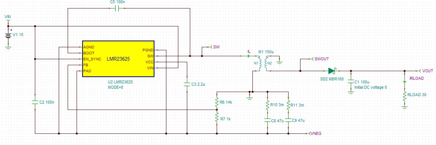
I've imported the unencrypted PSPICE model for LMR23625CF into TINA as shown below. (attached find simulation file)

NOTE: It would be really nice if TI could provide models for our own simulator.

This design requirements are Vin = 15V, Vout ~= 15V, Iout = 1A, with isolation, using only commonly available 1:1 coupled inductors or transformers for the magnetics.

In order for this circuit to work, the controller must use forced PWM and synchronous rectification, making the LMR23625 the least expensive first choice according to the parametric search table.  This is similar to a flybuck approach, except the primary side is wired up in the inverting buck-boost configuration.

This circuit seems to start working but then runs in a convergence problem, or otherwise seems a bit unstable.

Can you please take a look at this and let me know which direction to go?  The lack of external compensation on this device makes it a bit hard to use for anything beside a buck.

LMR23625 isolated supply.TSC

  • Hi Antenna head,

    I took a look and believe it could be a modeling program. The circuit looks good to me, so its possible the model cannot support this.

    I will contact the internal team and get back to you.

    Thanks,

    Ethan

  • Please take a hard look at the transformer.  I think part of the problem is there.

  • Possibly. I was able to get rid of the convergence error by changing the value of the coupled inductor to have the same inductance on both sides, but waveforms are still incorrect.

    Regards,

    Ethan

  • Hi Antenna_Head,

    I was unable to debug the TINA model and may forward this along to the modeling team to see if they have any inputs. I am working on a SIMPLIS model to confirm functionality.

    What is output current in the primary and secondary side. Is it 1A total? or each? Is their a customer behind this request and are they open to using a different topology for +15V and -15V? Is the wide input voltage required for this application?

    Regards,

    Ethan

  • The output is only on the isolated side, ~ +15V, up to 1A (15W), though a bipolar output could also be interesting it could be created using a diode bridge and tapped secondary.

      I am investigating push-pull in parallel (cascoded SN6505B) but that design is limited to about 12W, as well as a discrete controller, LM3150 with half-H bridge.

    Yes, there is a major customer behind this.  You can email me for details.  Input voltage is +15V +/- 5%. Primary need is for isolation, output regulation may be somewhat sloppy.

  • Also, the LM5160 (flybuck converter) might be a good candidate here.  It's SPICE model doesn't work either in the inverting configuration.  Seems like it wouldn't be that hard to create one.

    The LM5160 is rather pricey though compared to LMR23625, or even the more equivalent LMR23630.

  • Hi Antenna_Head,

    I have emailed you for more details. We can close this thread and contact offline.

    Thanks,

    Ethan