This thread has been locked.

If you have a related question, please click the "Ask a related question" button in the top right corner. The newly created question will be automatically linked to this question.

UCC28056: Can we achieve both PFC as well as flyback toplogy using the UCC28056, IC alone ?

Part Number: UCC28056
Other Parts Discussed in Thread: UCC28740, PMP11155, UCC28050, UCC28180, TINA-TI, UCC28700

I have to design a AC/DC power supply with specifications as follows: -

Requirements:  -

Input - 90 - 230 V AC.

Output - 17.2 V , 1.15 A ,  20 Watts.

Constraints: -

Power Factor - above 0.9.

Isolated flyback topology.

So, my questions are :- 

1) Can UCC28056 alone would be able to achieve both PFC as well as Flyback topology  ?

2) If not then, can I go for UCC28056 ( for PFC ) along with the UCC28740 ( for Flyback topology ) in the same circuit ?

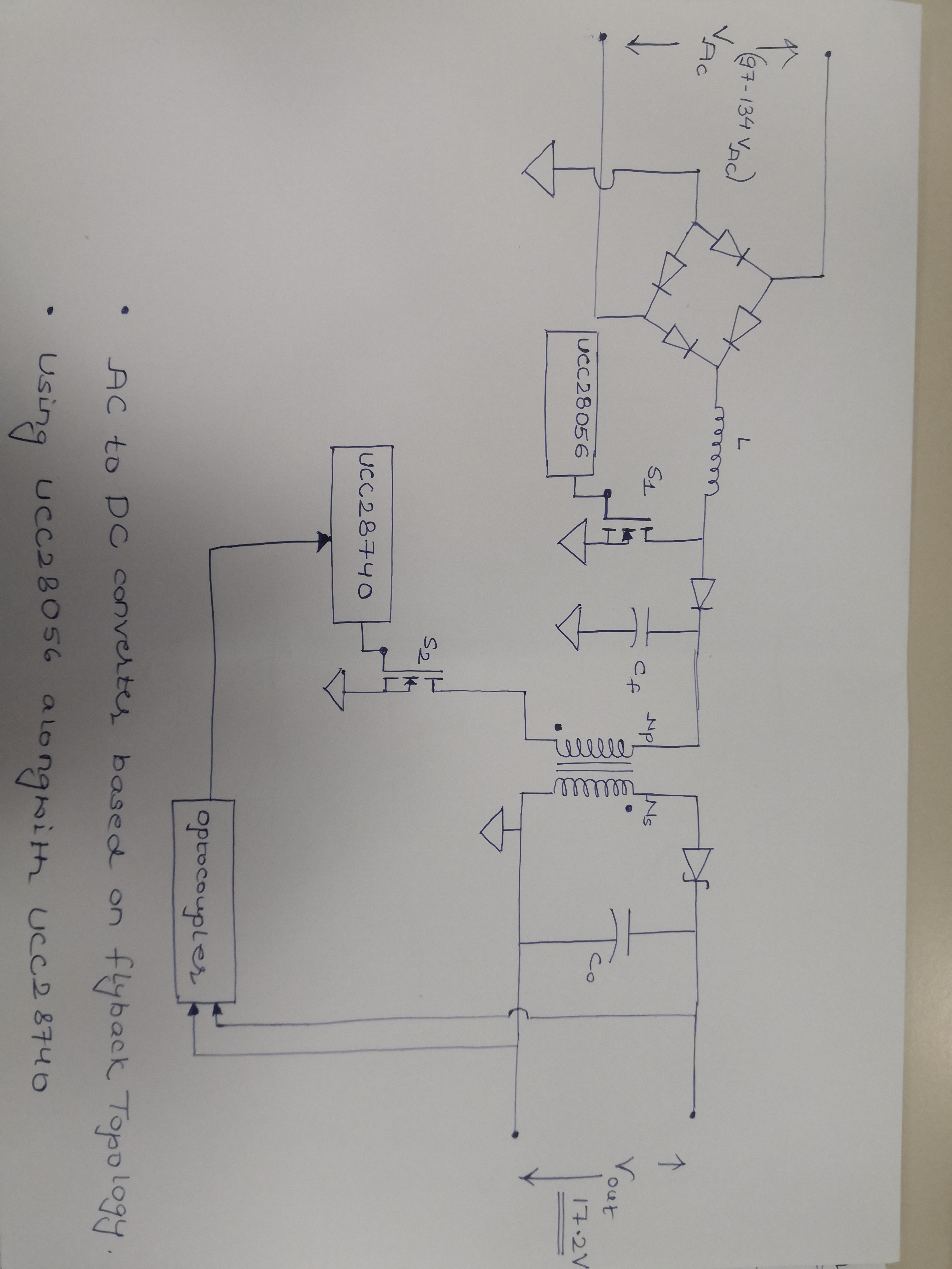
So, just as a reference to the 2nd question, I'm attaching the rough circuit diagram of the converter which will be using the UCC28056 along with the UCC28740. Will this circuit shown in the block diagram be able to achieve my requirements ?

please find the attached jpg file for block diagram below.

  • Vineet

    UCC28056 cannot meet your PF requirement when configured as a flyback.  If you would like a PFC flyback our 8 pin PFC controller UCC28050 can meet your PF requirements.  PMP11155 is an example of it working as a PFC flyback close to your target specifications. 

    You can configure UCC28056 (PFC Boost) + UCC28740 (flyback) to achieve higher performance in a two stage solution as you show.  Our recommendation is that you configure UCC28740 to startup when the PFC boost stage is disabled, then let the aux winding provide bias power to both UCC28740 and UCC28056.

    Best Regards,

    Eric

  • So, if I'm going to use UCC28056 (PFC Boost) + UCC28740 (Flyback) as shown in the block diagram I've shared. I have to make sure this AC-DC converter should be complying with the RTCA/DO-160 spec. Per the spec, the input supply frequency can vary from 360-800 Hz. So, can the PFC Controller device handle this frequency range?

  • Vineet

    UCC28056 is designed to work with utility frequencies from 47-63Hz.  UCC28056 will not be able to support an input frequency of 360-800Hz.  It will deliver power, but the input voltage sensing will be degraded so PF/THD will be poor.  

    Our CCM PFC controller UCC28180 can work better at 360-800Hz, we recommend that you use this device instead.  Please note that at these higher frequencies there will be increased distortion at the zero crossings.

    Best Regards,

    Eric

  • HI Eric,

    when I went for the simulation of the proposed circuit in the block diagram in TINA TI, I was not able to find the IC's ( UCC28180 & UCC28740 ) in the component list. I also looked for the PSpice models. so, that I can create a macro but, I wasn't able to do that. So, I'm stuck here and can not proceed for the simulation part as these IC's are going to be the heart of the circuit and if I'm not able to find them on TINA TI, Then I won't be able to proceed further.

    see if you can help me on this.

    Thanks,

    Vineet

  • Vineet

    TINA TI model for UCC28180 is available here

    UCC28740 does not have a TINA model.  It does have a SIMPLIS model that's available here http://www.ti.com/lit/zip/slum672

    If you need a TINA model of a low power flyback we recommend you use UCC28700, TINA model for UCC28700 is available here

    Best Regards,

    Eric

  • Hi Eric,

    Following the UCC28180 (PFC) Reference design of the EVM & the datasheet, I proceeded with the calculations according to my design requirement. But when I tried to simulate it in TINA-TI, I was getting the PFC Boost stage output as the output after the bridge rectifier stage.

    So, I checked with the TINA-TI model for the reference design and got to know it is using a block in place of the Mosfet. So, when I'm simulating my circuit by keeping the Mosfet then it is not working. But when I'm replacing the Mosfet of my circuit with the block used in reference design simulation, then it is working and I'm getting the desired output.

    I'm attaching both the TINA simulation files i.e.

    1) the standard one which is using Mosfet.

    2) Using an unknown Block (named as "BOOSTCCMDCM" ) in place of the Mosfet. 

    I have to simulate and get the output by using the Mosfet only. So, see if you can help me on this.

    Thanks,

    Vineet 

    With_Mosfet.TSC

    Without_Mosfet.TSC

  • Hi Vineet,

    The UCC28180 model is an average model and not a switching model. TI does not have a switching model for the UCC28180 to run transient switching simulations.

    Regards

    Peter

  • Hi Peter,

    My question was, if you look at the schematics of the reference design of UCC28180 you can see the typical switch (Mosfet) is being replaced with an unknown Block known as "BOOSTCCMDCM". So, I tried replacing the block with the Mosfet, but the simulation was not working at all.

    So, I need explaination for the block and why it is not working with the mosfet ?

    please have a look at the TINA-TI simulation files I've shared ( with mosfet and without mosfet ).

    Regards,

    Vineet.

    7183.Without_Mosfet.TSC

    5001.With_Mosfet.TSC

  • Hi Vineet,

    It is not possible to change the BOOSTCCMDCM with a Mosfet and get the simulation working.

    The simulation is an averaged model simulation and does not produce a gate drive signal to drive a mosfet. The average model is essentially a mathematically representation of the mosfet and diode, this is a good link on average model,

    The average model generally runs much faster than a switching circuit model which is very useful in PFC stages where the Voltage control loop is slow and it can take many cycles of the AC mains frequency, 20ms period, for the output to stabilize although the switching frequency can be 100kHz.

    Regards

    Peter