This thread has been locked.

If you have a related question, please click the "Ask a related question" button in the top right corner. The newly created question will be automatically linked to this question.

UC3875: UC3875 cuases unstable situation in PSFB

Part Number: UC3875

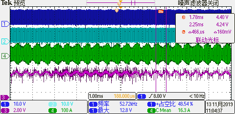
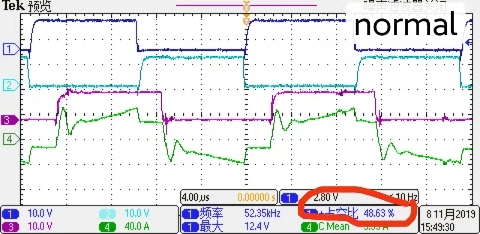
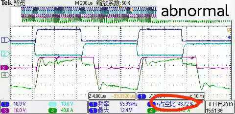
1.Two scope pictures were show as above. As in PSFB DC/DC converter,when the load became larger, for example from 2kW to 2.3kW, the situation became unstable. when it is abnormal, the duty of C and D is 0.42. When it is normal, the duty cycle should be 0.49. 

2.Why in unstable situation, the phase shift operation has been lost? 

3. I guess that UC3875 has been distorbed when the load changed from 2kW to 2.3kW, so the EAout is also changed. How can I improve this situation? 

  • Hello

    Does Vout decrease when you increase the load ?

    In normal operation the positive and negative half cycles are symmetrical - in the abnormal operation the positive half cycle looks normal but the negative half cycle is different to the positive half cycle. This might be due to noise coupling into the PWM comparator or the controller going into current limit on the positive cycles but not on the negative cycles.

    Can you identify the traces please ?

    Where have you placed the current transformer ? - you can send your schematic to me at colingillmor@ti.com

    if you don't want to post it here

    Regards

    Colin

  • Hi,

    Thanks for your reply.

    In the situation of increasing the load, the PSFB got into unstable situation, the average value of Vout didn't decrease, but the ripple became much larger. As it was 4V before in stable situation but now it bacame 26V.

    I cannot test the Uramp, EAout and  EA-,as it can cause sharp noise on the transformer. However, if I donnot put the probe on these pins, it's OK, the transformer doesn't cause noise.

    The photo of my prototype has been sent to your email.

    Best Regards,

    Ben. 

  • Hello Ben

    I think that the problem is due to noise in the system. Assuming Ch1 = OUTA, Ch2 = OUTB, Ch3 = OUTD and Ch4 is transformer current. In normal operation the A/D duty cycle and B/C duty cycles are the same so the current waveform is symmetrical. In abnormal mode it looks like the A/D duty cycle is ok but the B/C duty cycle is very short. This can happen if there is a large leading edge spike on the signal at the CS pin and this causes the PWM comparator to trip immediately to terminate the cycle by turning OUTC off.

    Can you take a look at the signal at the CS pin - you should use a tip and barrel technique to eliminate noise pickup from a long ground lead. Please check your layout and make sure that the filter capacitor between CS and GND is as close as possible to the CS pin and that the filter resistor is also close to the capacitor.

    4V of noise on the output is very high - can you take a plot using the tip and barrel method and post it here ?

    /cfs-file/__key/communityserver-discussions-components-files/196/0285.Tip-and-Barrel.pptx

    Regards
    Colin

  • Hello,

    Thanks for your reply.

    As you advised, I tried the tip and barrel technique to test the CS pin(CH3).


    As you can see from the scope, there is big noise in this pin. However, it has not exceed 2.5V whether in stable or unstable situation. By the way, the CS pin is connected to GND by a ZERO resistor.

    Now, I also test the EAout pin(CH3). It's true that when it came into unstable situation, the EAout also oscillated.

    The ripple of VOUT in stable situation is also tested as below.

    Partial of my schematic is sent to your email. Thanks a lot for youe help.

  • Hello Ben

    If CS is connected to GND then you must be using voltage mode control (VMC) - please confirm this. In VMC the CS pin is used for current limit purposes only so we can leave it as it is for now.

    The output noise contains a strong a sinusoidal oscillation at about 2.2kHz so I would suspect very that the control loop crosses the 0dB point with 0degrees of phase margin and is unstable as a result of this. The solution is to increase the phase margin - ideally to about 60 degrees but anything above 45 deg is often considered to be sufficient. Please look at the training material at the following links.

    For VMC you should be using a Type 3 compensator to get the best bandwidth. For now, I'd suggest that you slow the loop response right down, at least by a decade to 200Hz or even two decades to 20 Hz. This should stabilise the loop, although the response times will be longer than you would want, giving you an opportunity to study it and to apply the techniques outlined in the material below. I think your should play the training video first because it is a basic introduction to stabilising control loops.

    http://www.ti.com/lit/ml/slup098/slup098.pdf 

    https://www.ti.com/seclit/ml/slup113/slup113.pdf

    https://training.ti.com/control-smps-refresher?keyMatch=REFRESHER&tisearch=Search-EN-everything

    I will need to see your full schematic before I can offer much  more advice. Please let me know how you get on.

    Regards

  • Hello Ben


    We haven't heard back from you for a while so I assume the question has been resolved so I am closing the thread. If I am mistaken you can always open a new, linked thread.

    Regards

    Colin