This thread has been locked.

If you have a related question, please click the "Ask a related question" button in the top right corner. The newly created question will be automatically linked to this question.

LM3409: LED current ripple recommendation

Part Number: LM3409
Other Parts Discussed in Thread: INA169,

Hi team,

I would like to ask if the LD Current is to be controlled within +/- 6% (including Ripple noise), if it is applied with LM3409HV.

1.) How can we modify the surrounding schematic as below link to achieve it? 
2.) If the INA169 current sensor is connected in series with the LED driver Output, then it is detected by the MCU ADC Pin, and  then used to dynamically adjust the LM3409HV IADJ to correct the current, is it feasible, or is there any other suggested way? Thanks.
 
https://txn.box.com/s/qtqupdiwpj2mrsbk8nyp5yfm2ba0d68g

  • Hello,

    I cannot open the file, they are discontinuing the use of this.  Is this the same schematic as the previous LM3409 post?

    1)  Output current ripple will depend on the switching frequency, inductor, Vin, Vout, Dynamic impedance of the LED string and output capacitance.  Increasing the inductor value and/or increasing the switching frequency will reduce ripple.  Added output capacitance will also reduce current ripple. One can also add some series resistance to the LED string though that is less desirable due to losses.

    2)  That can work however how are you going to power the IN169?  Are you planning on sensing on the bottom of the LED stack?  It makes more sense to implement current sense on the bottom side of the LED stack.  It is referenced to ground on that side.

    Best Regards,

  • Hello,

    I haven’t heard back from you, I’m assuming you were able to resolve your issue.
    If not, just post a reply below (or create a new thread if the thread has locked due to time-out).

    Best Regards,

  • Hi Irwin,

    Thank for your help.

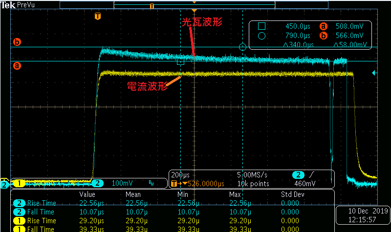
    Customer doesn't doubt about our LED driver can achieve constant current without overshoot.
    From their measurement waveform, it didn't show the overshoot behavior on current waveform.

    CH1: current waveform CH2: brightness
    But, the problem is that the raser will have better light efficiency to induce the overshoot of brightness since startup of raser and the brightness of LED will be higher even the current is the same as stable situation. Raser manufacturing said that it will influence the life cycle of raser and also couldn't support higher current capability. Reducing slew rate of LED driver is not a option for customer due to the strictly spec on slew rate from our DLP chipset.

  • Hello,

    If you are reading current and the MCU can adjust Iadj it can be used to adjust the current open loop to try and reduce the light overshoot.  Open loop can have issues depending on how consistent the operating conditions are.  What is the highest duty cycle this will run at?  Are the laser pulse widths constant?  Is the duty cycle constant?  Is the output power constant when on?  What does the manufacturer of the laser say about how to drive the laser to get constant light output?  Does it require a feedback from sensing the light output?

    Best Regards,

  • Hi Irwin,

    Thank for your kindly help.

    About the system design detail of compensation of laser light, I am not the expert of the laser.

    I will show to customer our suggestion and let customer decide whether the implementation is reasonable for them.

    There is another project which is also using LM3409 and customer would like to consult with you about the feature of Coff.

    The load spec of their load (TEC) is as below:

    Working voltage: 0V ~ 35V

    Load current: 0 ~ 7A

    In the LM3409 specification, when the light load happened the output voltage is always less than 1.24V, TOFF will be limited to 300us, causing the output current to be discontinuous.

    1. Is there any way to prevent this situation at light load?
    2. If they apply a external voltage into VCOFF to prevent the vout will be less than 1.24V, is it feasible? Would you have any concern about it?

    3. Do we have calculation excel tool of LM3409

  • Hello,

    1)  Yes, see section 8.3.8 in the LM3409 datasheet.  When Vled gets to low to charge the off-time capacitor the second Roff allows it to charge. This keeps the current regulation more accurate then using a fixed Roff voltage.

    2)  An external voltage will also work however they will lose current regulation accuracy versus output voltage.  The Roff resistor is still needed.  This controls the charge rate of Coff which is how long the LM3409 is off after hitting the peak current threshold.

    3)  I don't believe there is a calculation tool however it is a fairly simple part to design around using the datasheet equations.

    Best Regards,