This thread has been locked.

If you have a related question, please click the "Ask a related question" button in the top right corner. The newly created question will be automatically linked to this question.

TPS23750: TPS23750 Evaluation Board – HPA107 doesn't or scarcely detect PSE connecting to NETGEAR GS350P PSE.

Part Number: TPS23750
Other Parts Discussed in Thread: TPS2378EVM-105

Hi, there.

We are developing  PoE Appliance for an particular client.

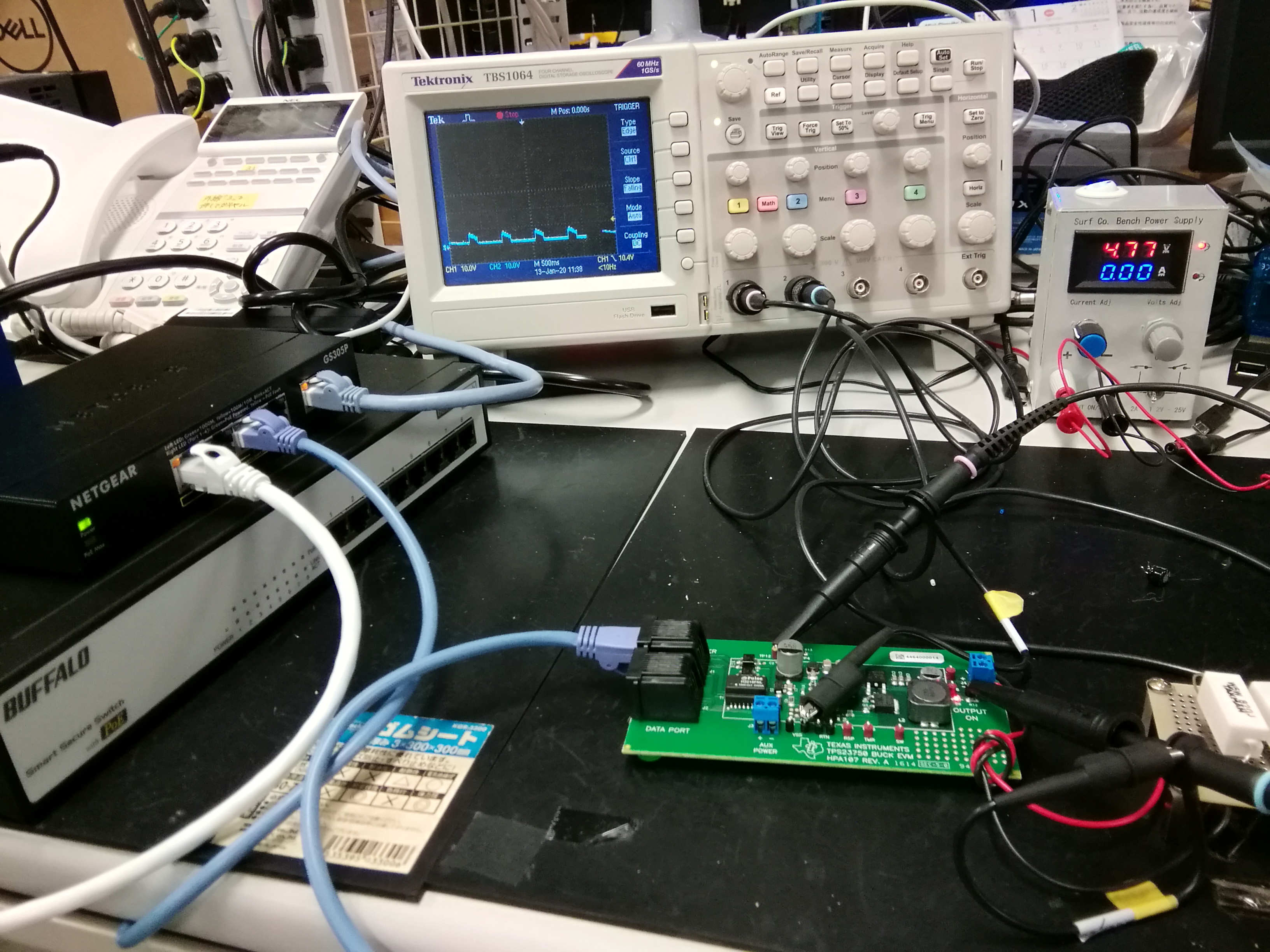
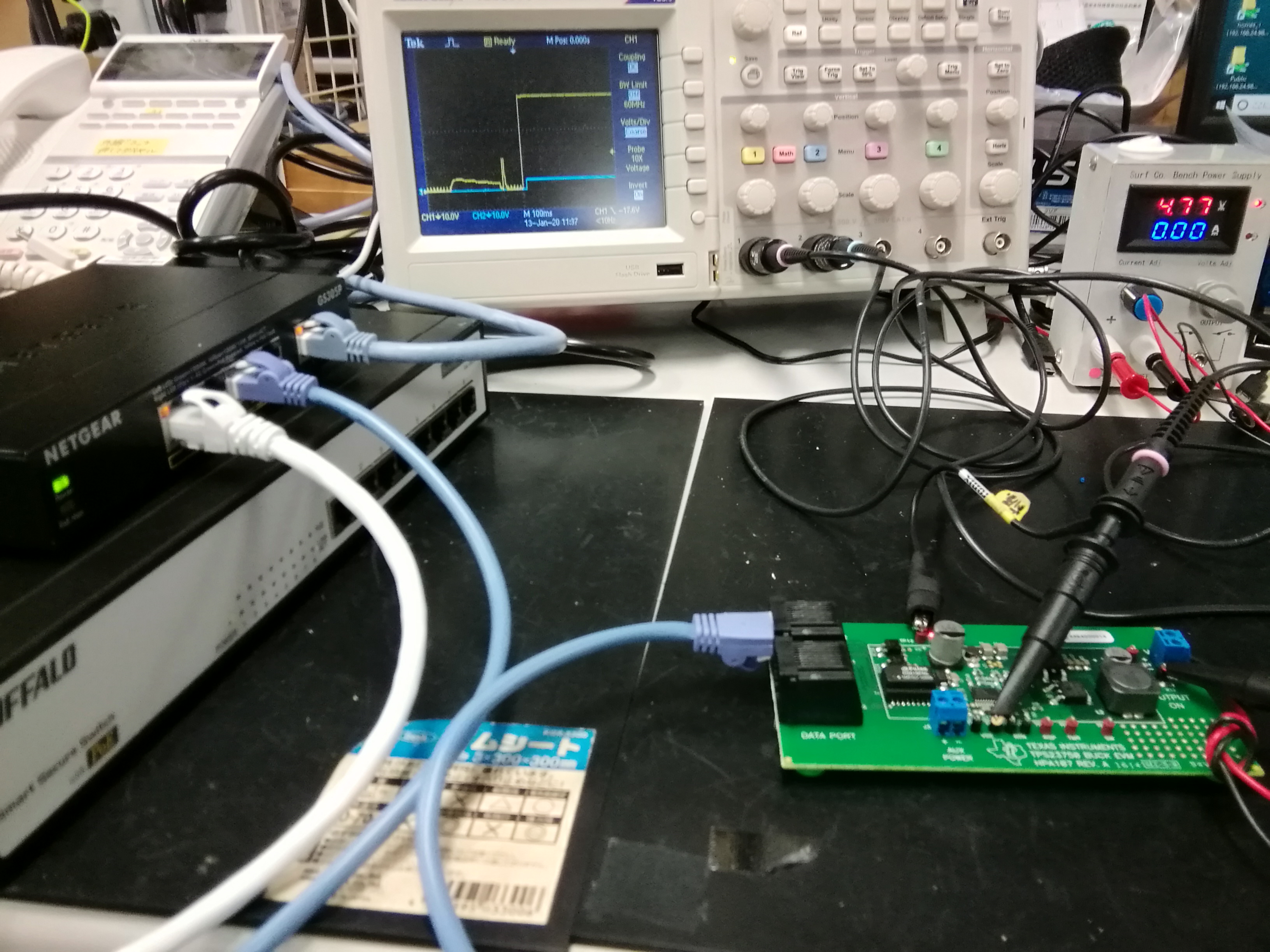
I'm designing 5V 1A Poe Power referring TPS23750 HPA107 Evaluation Board.

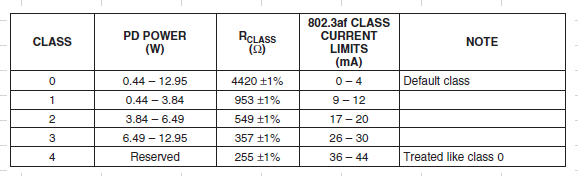
I amended Class defining register R3 from 357 Ohm(Class2) to 549 Ohm(Class2).

Current detecting register R10 from 0.15Ohm to 0.51 Ohm.

It should be supposed to work as Class 2 5V/1A PD.

Actually, It works well with BUFFFALO BSL65-PS-2100M(IEEE802.3af 15.4Wx8) it works good as expected.

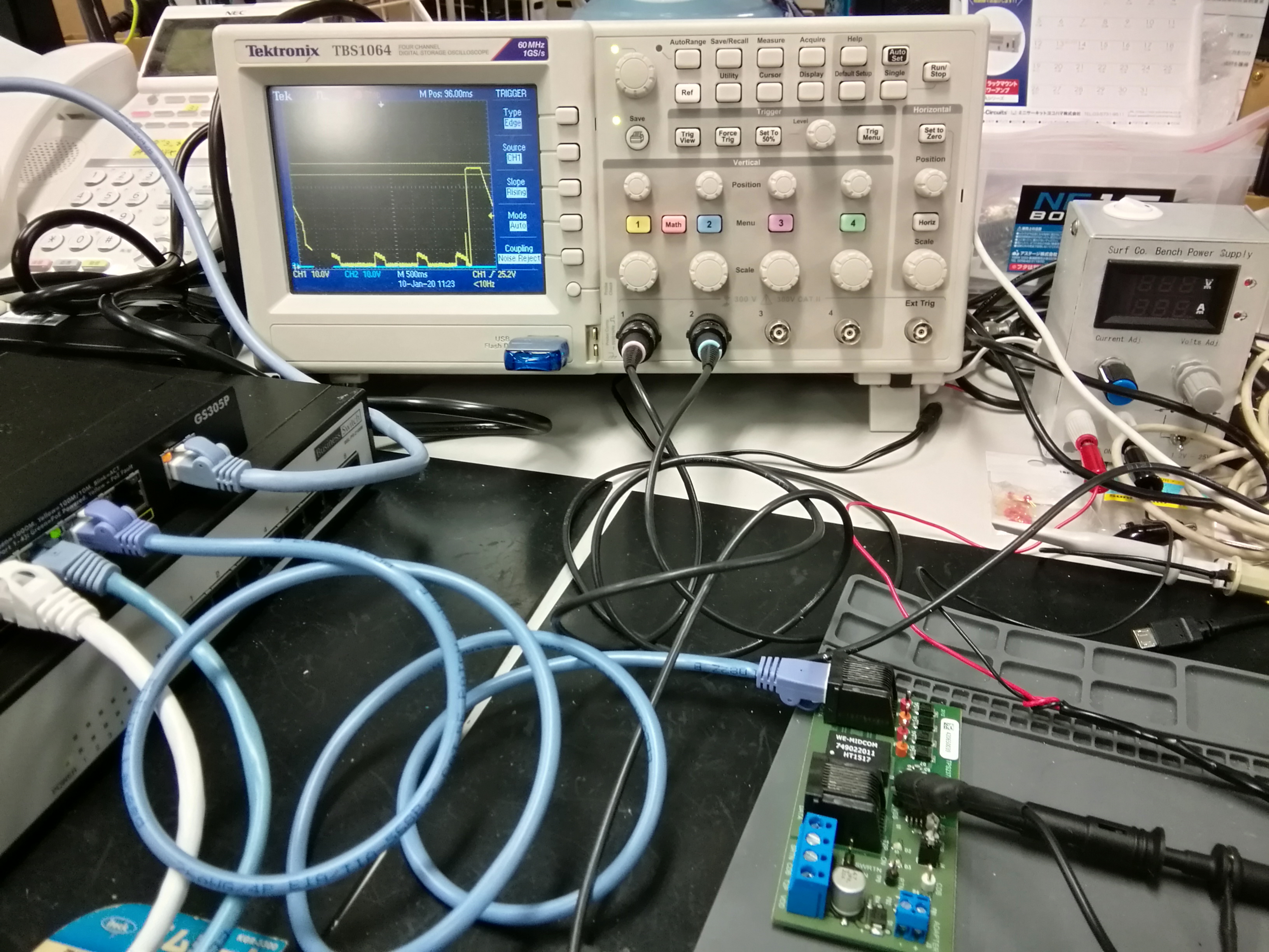
But unfortunately I have changed to some NETGEAR or TP-LINK PoE switching hub, it doesn't work correctly.
NETGEAR GS305P spec is also (IEEE802.3af 15.4Wx4).

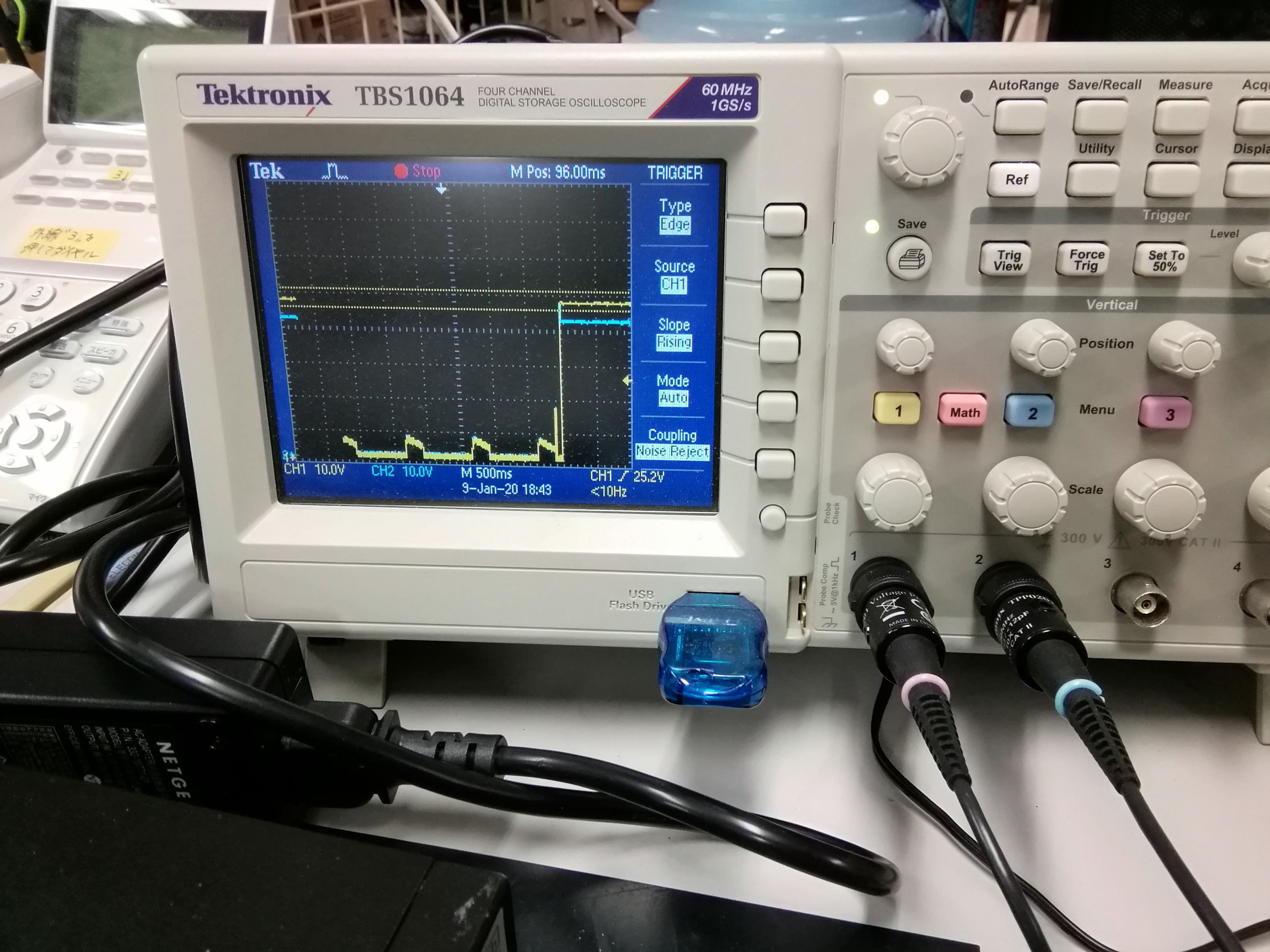
The symptom is , PoE LED and 5V LED blinks periodically each 3 to 5 seconds with no load.

With dummy load, it recognize after 5 to 10 times PD sense from the NETGEAR hub.

I guess it is caused by my amendment, then I bought new HPA107 Evaluation Board, and tested but result was same.

I changed the cables also.I don't understand what is happening.

I would like to attach some photos w/ Ti eva board voltage waveform.

Your Help is Highly appreciated.

Best regards

  • Hi ,

    I would guess the PD board doesn't provide a valid MPS(maintain power signature) to PSE to keep the PSE port on. There are two ways to verify:

    1. Measure port current while the PD board doesn't work with the PoE switch.
    2. Add some class 2 load to the PD output and see if the port can be turned on successfully. 

    Best regards,

    Penny

  • Hi, Penny-san

    Thank you for your respond.

    I tested with other PD like IP Phone(I guess it is Class0) and detected normally.

    I think it is strange that a brand new TPS23750 Evaluation Board – HPA107 also doesn't work, because it is TI's reference design.

    I tested with TP-link TL-SG1005P 5port PoE hub (IEEE802.3af 15.4Wx8)as PSE also.

    It also same thing happen( PoE LED and 5V LED blinks periodically each 3 to 5 seconds with no load).

    I checked again TPS23750 HPA107 Evaluation Board data sheet and TPS23750 IC datasheet,

    It has DET terminal connected to PoE + with 24.9kOhm/1%.

    I didn't any amendment to this original board, so it is fixed value.

    Then I tried to connect TI other EVA board TPS2378EVM-105.

    This board also same thing happen...( PoE LED and 5V LED blinks periodically each 3 to 5 seconds with no load).

    (Please refer to attached picture)

    Then, I connected about 250mA load to TPS23750 HPA107 Evaluation Board 5V output, the trouble seems improved a little.

    (It detects PD after 5-20 times try, and PSE output 48V constantly) I suppose 5V load and PD detection is no relation.

    It is caused by PoE Hub compatibility or some ?

    Could you please help usto solve  this strange things have happen.

    Regards,

  • Hi, Penny-san

    Thank you for your respond.

    I guess I didin't understand what MPS means.

    In TPS23750 datasheet shown below, page 15 describes about MPS

    >The PSE may then power the PD if it has adequate capacity. Once
    >started, the PD must present the maintain power signature (MPS) to assure the PSE that it is still there. >The PSE
    >monitors its output for a valid MPS, and turns the port off if it loses the MPS. Loss of the MPS returns the >PSE tothe initial state of detection. Figure 29 shows the operational states as a function of PD input >voltage

    But I don't understand how to control MPS in the reference design.

    I fond increasing load current improves this phenomena, but could you tell me how to improve in design ?

    For example, change class 2 to class 0 improve this MPS check ? (minimum 3.84W to 0.44W)

    Could you please advice me the solution ?

    Best regards,

  • Hi, Penny-san

    I forgot to ask you another problem that initial PD detection is unstable.

    (first post, first picture.)

    It depends just TPS23750 resister 24.9k/1% Ohm attached to DET terminal. (is fixed)

    Could you please advice me how to improve this phenomena and reason why?

    Best regards,

  • Hi ,

    Since there's no load connected to TPS23750EVM and TPS2378EVM and the board itself's power consumption is very low, it is possible that the current going through the CAT 5 cable is very low and not meeting the MPS requirement. You have to add some load to the EVM output to make sure the PSE port current is >10mA. The MPS has nothing to do with the class resistor and it is only related to your load. In your case, you can add 5W load and see if the port keeps on. To answer your detection question, as long as your detection resistor is in the range of 19K to 26.5K, it should be good. PSE may use some software to control the port. Thus, it may takes several cycles of detection and classification before the software makes the decision to turn on the port. An easy way to verify your PD's interoperability  is to do sifos test with your PD and make sure it it IEEE compliant. Thanks. 

    IEEE standard defines the MPS requirement as below. 

    Best regards,

    Penny

  • Hi, Penny-san

    Thank you for your kind respond.

    Due to your detailed explanation, I somehow understood cause of those PoE detection issues.

    issue 1: PoE LED and 5V LED blinks periodically each 3 to 5 seconds with no load.

               Cause:TPS23750EVM and TPS2378EVM with no load are not meeting the MPS requirement.

               Solution: We have to add some load to the EVM output to make sure the PSE port current is >10mA.

              (No relation to PD class.)

    issue 2:Another problem that initial PD detection is unstable. (PSE tries 5-10times to detect PD.)

              Cause: Without oscilloscope probes connection, they recognize PD soon. (later information from last post)

                         Somehow  prove ground to Vss TP1 makes it unstable. (attached picture 1)

                         I tried to connect oppositely (+48V -ground pin, Vss -prove pin) and display CH1 and CH2 invert. (attached picture 2)

                       BINGO! It success!! this time NetGesr PSE detected every 1st time!

            Solution: Be care to connect oscilloscope probes when operation checks especially around PoE Vss.


     Thanks a lot for your assistance and advice.

     I'm not familiar with the PoE equipment, but due to your help I have learned  many things to know about PoE in such a short time.

    Best regards,        

                Solution:

  • Hi ,

    Thanks for the updates and I am glad to see the issues were resolved. Thanks.

    Best regards,

    Penny