This thread has been locked.

If you have a related question, please click the "Ask a related question" button in the top right corner. The newly created question will be automatically linked to this question.

TPS65910: TPS65910A3A1RSL PMIC is not Working Vref =0v .

Part Number: TPS65910
Other Parts Discussed in Thread: AM3352,

Hi,

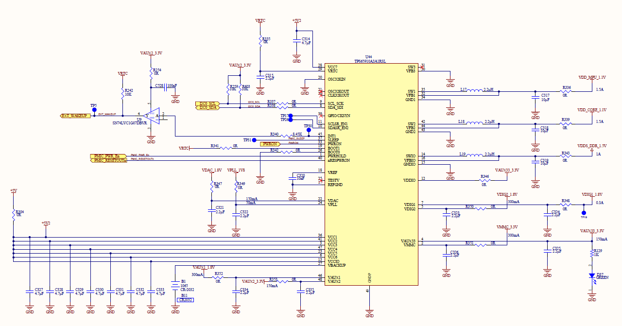
Regarding this PMIC  TPS65910A3A1RSL.


The Problem is we are not Vref Voltage is Zero even though VCC7 is provided 5V and also we are getting VRTC= 1.8V .

We have tried changing the PMIC Also but still the same behaviour.

Please let us know what could be the problem and which things may impact the VREF.

Please provide us some suggestions.

We have interfaced this IC with AM3352 processor.

Regards,

Vinay.

  • How are the BOOT1 and BOOT0 pins terminated? BOOT1 = RTC, BOOT0 = GND is the correct wiring for TPS65910A3+AM3352 processor (see User's Guide).

    What happens when you press the push-button connected to PWRON pin of the TPS65910 PMIC? If the PMIC powers on after a push-button press, then it means the BOOT1/0 pins are not connected properly.

  • Hi Brian,

    Here as we press the power on switch, PMIC is powering ON and As soon as we release the switch it is Powering OFF.

    And BOOT1 is connected to VRTC and BOOT0 is Connected to GND and connections are also proper.

    please find the attached schematic design for the reference and suggest us what can be impacting.

    Regards,

    vinay.

  • Hi Brian,

    When we press the poweron button, PMIC is giving the output voltages BUT as soon as We release the poweron switch, PMIC is powering OFF again.(Only VRTC voltage is coming)

    The Boot1 pin is connected to VRTC and BOOT0 is connected to GND and connections are also proper.

    Please find the attached schematics and let us know what could be the issue.

     ).

    Regards,

    Vinay

  • Vinay,

    Please determine is the voltage at TP5 is high (1.8V) or low (0V).

    It looks like U9 is a buffer for the INT1 signal from the PMIC that receives power from VAUX2_3.3V.

    Logically, this tells me that it does not have power and TP5 signal will be high (~1.8V). The name of this signal is EXT_WAKEUP on the processor side.

    If INT1 (EXT_WAKEUP) is not seen low by the processor, then PWRHOLD will not be set high. In order for the power-up sequence of the TPS65910 to start, PWRHOLD needs to be set high. Otherwise, only VRTC will be enabled (exactly as you have described your issue.

    Also, recommended value for VREF capacitor is 100nF, but in your schematic C320 is listed as 10nF. I recommend that you change this value on your schematic if you do an ECO for other schematic/BOM updates.

  •  Hi Brian,

    We have tried by making the EXT_WAKEUP signal to be PULLED DOWN to GND and removed the VRTC pullup.

    Now at TP5 voltage is 0V, but still The PMIC is not powering ON.

    And I have a doubt like how the processor will send the PWRHOLD signal without the power supply coming from the Outputs of PMIC.

  • Venkata,

    Did you try changing the value of VREF capacitor to 100nF? In your schematic C320 is listed as 10nF, but the recommended value is 100nF.

    The only other thing I can think of would be that you are using the TPS65910A3A1RSL version of the device, which turns on with the RTC LDO in low-power mode (VRTC_REG.VRTC_OFFMASK = 0).

    My recommendation is that you order samples of the TPS65910A31A1 device and test in your system, with RTC LDO in full-power mode (VRTC_REG.VRTC_OFFMASK = 1) at system turn-on.

    According to the User's Guide for powering AM335x with TPS65910Ax:

    If the current load exceeds 0.1 mA before the VRTC pin is 1.8 V and the OTP loads, then ... the device stays  in the NO SUPPLY state.


    This is similar to the problem you describe where no other rails can turn on except VRTC

    Venkata vinay kumar Ganjikunta said:
    And I have a doubt like how the processor will send the PWRHOLD signal without the power supply coming from the Outputs of PMIC.

    The RTC domain is very low-power. The RTC domain (VRTC) supplies power to PWRHOLD signal, and PWRHOLD must be set high before the power-up sequence starts (VDAC is first main rail to turn on). I stand by my statement that INT1 (EXT_WAKEUP) must be low for PWRHOLD to be set high. See below timing diagram from User's Guide which shows VRTC before PWRHOLD and PWRHOLD before VDAC.

  • Hi Brian,

    we have tried with the TPS65910A31A1 IC. we have changed VREF cap to 100nF but still it behaving the same.

    Regards,

    vinay.

  • Hi Vinay,

    Brian is out of office today but will respond back tomorrow.

  • Vinay,

    How many boards have you built and how many experience this issue? In other words, what is the rate of failure?

    VREF is critical to the operation of the device. If VREF = 0V, then it is not guaranteed that anything will work correctly.

    The following is from the TPS65910 datasheet.

    Datasheet page 17, Power References and Thresholds section 5.9 - Output reference voltage (VREF terminal): Device in active or low-power mode 0.85V +/-1% 

    Datasheet page 45, Power Reference section 6.1 "The bandgap voltage reference is filtered by using an external capacitor connected across the VREF output and the analog ground REFGND (see Section 5.3, Recommended Operating Conditions). The VREF voltage is distributed and buffered inside the device.

    If the reference voltage is not available, to me this indicates a schematic wiring or assembly error that is causing the device to malfunction.

    The only debug methods I can suggest at this moment is:

    1. Carefully inspect the PCB and compare to your schematic and the TPS65910x Schematic Checklist (Rev. B) provided by TI, looking for possible errors
      • For example, what is the purpose of R304? +5V and +5V2 should not be applied simultaneously, yet it appears that R304 is not marked as DNP
    2. Try testing three ways while measuring VREF and VRTC: VBACKUP (coin call) and VBAT (+5V2), VBAT only (coin cell removed), and VBACKUP only (main power not applied. What is the voltage on VREF and VRTC under each condition? Does it change?

    It is my understanding that only VBAT and VBACKUP can have an impact on whether or not VREF turns on. If the part is soldered down correctly, then an issue with either of these supplies could cause an issue with VREF. VREF must be 0.85V+/-1% for the PMIC to operate correctly.