This thread has been locked.

If you have a related question, please click the "Ask a related question" button in the top right corner. The newly created question will be automatically linked to this question.

TPS65150: TPS65150 Inrush current of VIN when Vs(AVDD) start up(or soft start)

Part Number: TPS65150

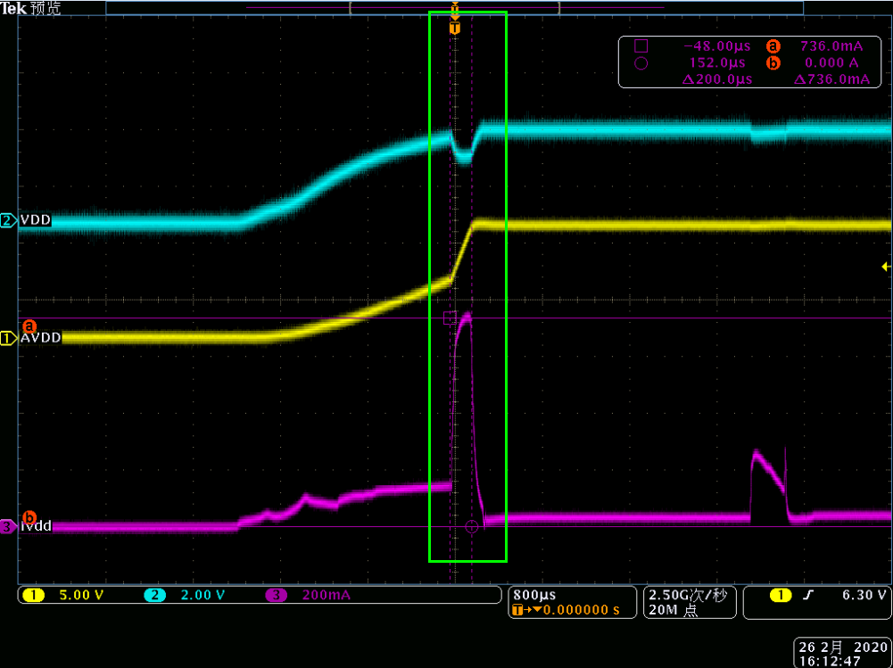
Hello, when I test the Inrush current of VIN(VDD), there is a big current when Vs(AVDD) start up. Please refer to  the picture1. It looks like there is two steps when AVDD start up, and in the first step, the skew rate is low, so the Inrush current of VDD is low. And in the second step, the skew rate of AVDD is higher, so the current is higher.

Is there any method to reduce the Inrush current in the second step?

I set 2 10uF capacitors on the AVDD, but even if I delete all the capacitors, the current is  about 500mA. And I'd like to reduce the current to 300mA.

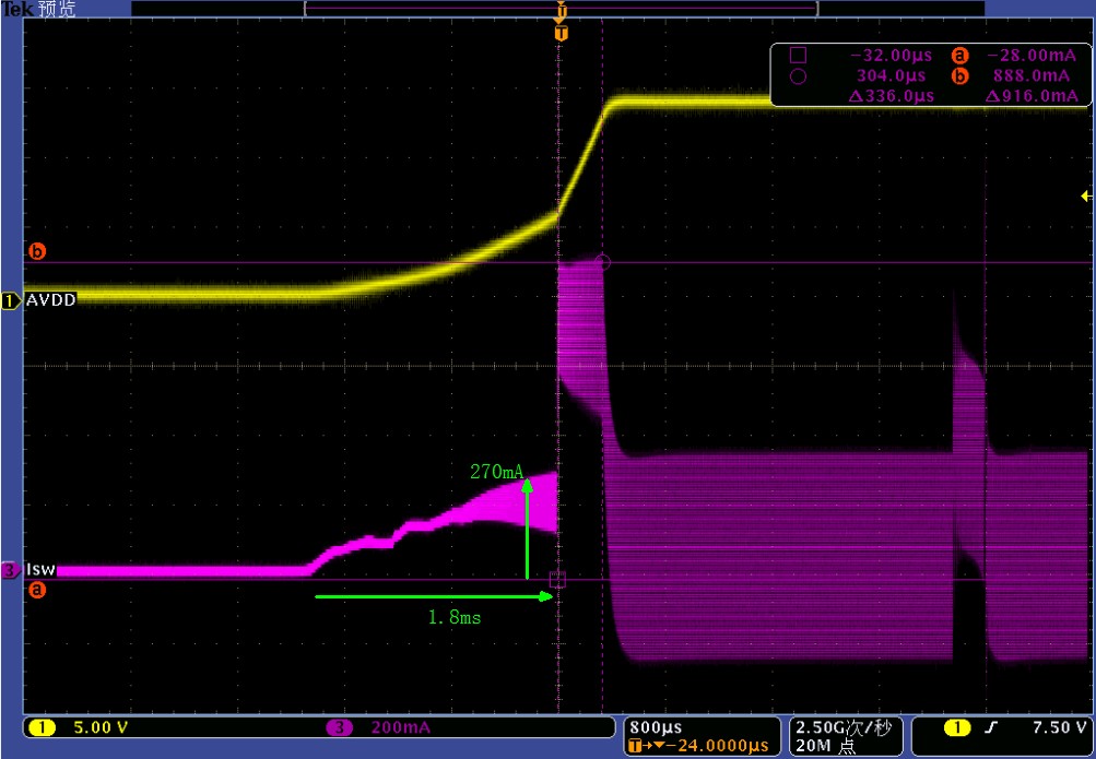
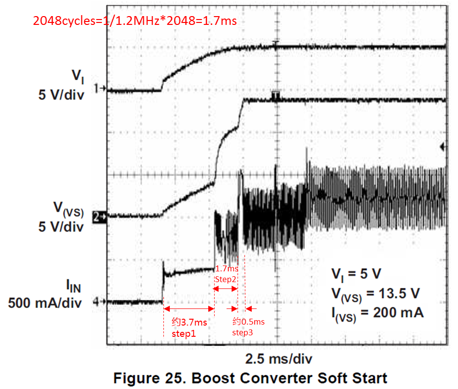
And also, according to the TPS65150 Datasheet, TPS65150 has soft start function, I want to confirm is there any relationships with the current of step 2? But  actually I don't see 3 steps when I test the switch current (current of Inductance).


  • Hello,

    Thank you for your post. We will look into it in detail provide any feedback by 3/2/20 or earlier.

    Kind Regards,

    Liaqat

  • Hello,

    Number of steps in the boost output will depend on the output capacitance and set the output voltage and if capacitance is smaller, it is possible that it is fully charged by the time the third stage current limit is released (100% switch current limit). So that is why you may be seeing only two steps in your application. Softstart current limits are fixed so I don't see a way to further reduce inrush current to 300mA which very low. Please see datasheet figure 25 which clearly shows this three step softstart current limit.

    During the first 2048 switching cycles, the boost converter's switch current is limited to 40% of its maximum

    value; during the next 2048 cycles, it is limited to 60% of its maximum value; and after that it is as high as it must

    be to regulate the output voltage (up to 100% of the maximum).

    Kind Regards,

    Liaqat


  • Hello

    How to calculate the maximum value of switch current? I didn't see the 40% or 60% from my test result. And I increase the output capacitance to 60uF(10uF*6), and the output voltage to 15V, but I didn't see the third step.

    And the time  for the first and second step is 2048cycles, but the first step is not 2048cycles(1cycle=1/1.2MHz),please see Figure25 in the Datasheet, and also the current in the first step is not 40% the maximum current(current of the third step).

    Please help to answer my questions. Thanks!

  • Hello Could you help to answer my questions? Thanks~

  • Hello,

    As shown in figure 25 (pasted above in your post) this waveform was measured into a load at start up. Did you measure into a load also? If you measure into a load under similar conditions, you should see a similar waveform. In any case what is the concern with two step or three step?

    As for the timing of the first step not being 1.7ms in the picture you pasted above, consider two points: part of first step involves time when boost output is simply following the power supply input before the switching even starts. Furthermore, switching frequency is note stable initially as the Vout starts to ramp up so one can not assume 1.2MHz as see seen later on in the ramp up. Lastly, 40%, 60% of current limit are not specifications of this device so they can vary widely. Only parameters listed in the "Electrical Characteristics" section of the datasheet are the specifications.

    Please see application note in the link below which has a section on how to calculate switch current.

    http://www.ti.com/lit/an/slva372c/slva372c.pdf

    Kind Regards,

    Liaqat