This thread has been locked.

If you have a related question, please click the "Ask a related question" button in the top right corner. The newly created question will be automatically linked to this question.

LM5122: Making of negative buck

Part Number: LM5122
Other Parts Discussed in Thread: LM5116, LM5112,

Dear engineers,

First of all, I will try to explain my situation:

I need to make symmetrical power supply +/-30V @15V:

Input voltage is 75V

For the positive side, I chose LM5116.

For the negative side I would like to use LM5112 like negative buck:

Here you can find my design for the negative side: zaporna cast v1.pdf

Since LM5112 can stand only 65V, I made a simple voltage regulator with Zener and NPN.

I would like to ask you a few questions about my design:

  • Is it possible to calculate the external components the same way as in LM5116 (positive buck)?
    • As a template, I used this designof positive buck with LLM5116
      • As you can see I used the same Rt, Css, input and output capacitors, inductor, compensation network
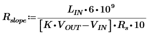
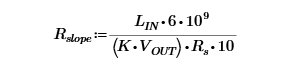
  • Since LM5122 has a different principle of slope compensation, I would like to ask you how to deal with this problem.

Many thanks for your reply.

  • Hi Martin,

    Thanks for your question. I can take a look at this in more depth and give you a response by Tuesday.

    Thank you,

    Richard

  • Hi Martin,

    You should be able to size the power-stage the same way as the LM5116 (Inductor, Input/Output Capacitor, MOSFET, compensation) as long as the input of the negative buck matches that of the input of the positive buck- since the transfer function should be the same.

    However, you should make sure that the LM5122 settings are the same as that of the system (so make sure UVLO, RT, and SS and other system parameters match that of the LM5116 circuit). Then, you will need to check for the protection circuitry.

    As for slope compensation, you need to make sure that the addition of your external slope comp is at least half of the down slope of the inductor current, so you will need to size R_slope accordingly.

    Additionally, your input/output capacitors should be placed respectively from the input/output to GND. Please make sure the polarity matches that required of your electrolytic capacitor. 

    Thanks,

    Richard

  • Hi Richard,

    How to determine the proper value for R_sense?

    Should I use instead of this equation :

    (Equation 6 from LM5122 Manual )

    this modified equation?

    Many thanks for your reply.

    Martin

  • Hi Martin,

    I believe equation 6 in the datasheet may have a typo, or is experimentally derived, so I can show you how I theoretically got a different equation.

    In your negative buck converter, your down slope is equivalent to (-Vin+Vout)/L, where Vin and Vout are the magnitude of your input and output. In order to prevent subharmonic oscillation, your additional slope should be at least 0.5*inductor down slope. In this case, I will call this factor (0.5) K. The slope generator in the IC is equal to (6*10^9)/R_slope.

    Therefore, I will set these two values to be equivalent:

    (6*10^9)/R_slope = (K)*(-Vin+Vout)/L*(Rs)*10; Rs*10 comes from the sensed inductor current. Here, in order to prevent a negative resistance value, you take the magnitude of (-Vin+Vout).

    In the end, Rslope = [(6*10^9)*(L)]/[Rs*10*K*(|-Vin+Vout|).

    Hope this helps,

    Richard

  • Hi Richard,

    I have one additional question:

    I am a little bit confused why down slope of a negative buck converter is equivalent to  (-Vin+Vout)/L.

    In this TI document on page 6, I found this :

    For any mode of operation (peak, valley or emulated), the optimal slope of the ramp presented to the modulating comparator input is equal to the sum of the absolute values of the inductor upslope and down-slope scaled by the current-sense gain. This will cause any tendency toward subharmonic oscillation to damp in one switching cycle.

    For the buck regulator, this is equivalent to a ramp whose slope is VIN · Ri / L.
    Up-slope = (VIN - VO) · Ri / L
    Down-slope = VO · Ri / L

    For the boost regulator, this is equivalent to a ramp whose slope is VO · Ri / L.
    Up-slope = VIN · Ri / L
    Down-slope = (VO - VIN) · Ri / L


    In fact, I use a positive boost IC to implement a negative buck converter.

    According to your explanation, it seems that I should use down slope equation for the boost converter. Am I right?

    Could you please explain to me why?

    Many thanks.

    Martin

  • Hi Martin,

    Sorry for the delay.

    The paper you have bought up is representative for a positive buck-input converter. 

    In that case, during the switch on-time, the inductor current has a slope of (Vin-Vo)/L. Since Vin is larger than that of Vo, the slope is positive. 

    In your negative buck converter, during the switch on-time (since you connected it to LO), the KVL equation will look like this: -(-Vin) + V_L+(-Vout) = 0; so V_L = -Vin+Vout. Through the magnitudes of your input and output voltage, your slope will be negative. Because peak-current mode uses slope compensation based on the negative slope, this is why you the equation I used above.

    I think the reason it may look somewhat similar to that of the boost converter is that the buck converter and boost converter are duals of each other (as in they use the similiar topology, but have flipped inputs and outputs). Assuming a unidirectional current flow, the slopes are flipped because the polarity of the inductor are also flipped depending on the direction of the current flow. 

    Therefore if you calculate the up and down slopes of the buck and boost converter while maintaining consistent polarity of the inductor between the two topologies and using their respective main switches, you will find that they look identical. I hope this helps. 

    Nevertheless, I would focus on understanding what your negative buck converter will look like during the on and off-time of the switch and calculating the voltage across the inductor for each case (the polarity across the inductor voltage should remain constant in order to make sure you do not violate volt-second balance principle). 

    Thanks,

    Richard