


Customer is now testing a board using two TLV62585 for generating the 3.3v and 1.8v power. The schematic is like below:
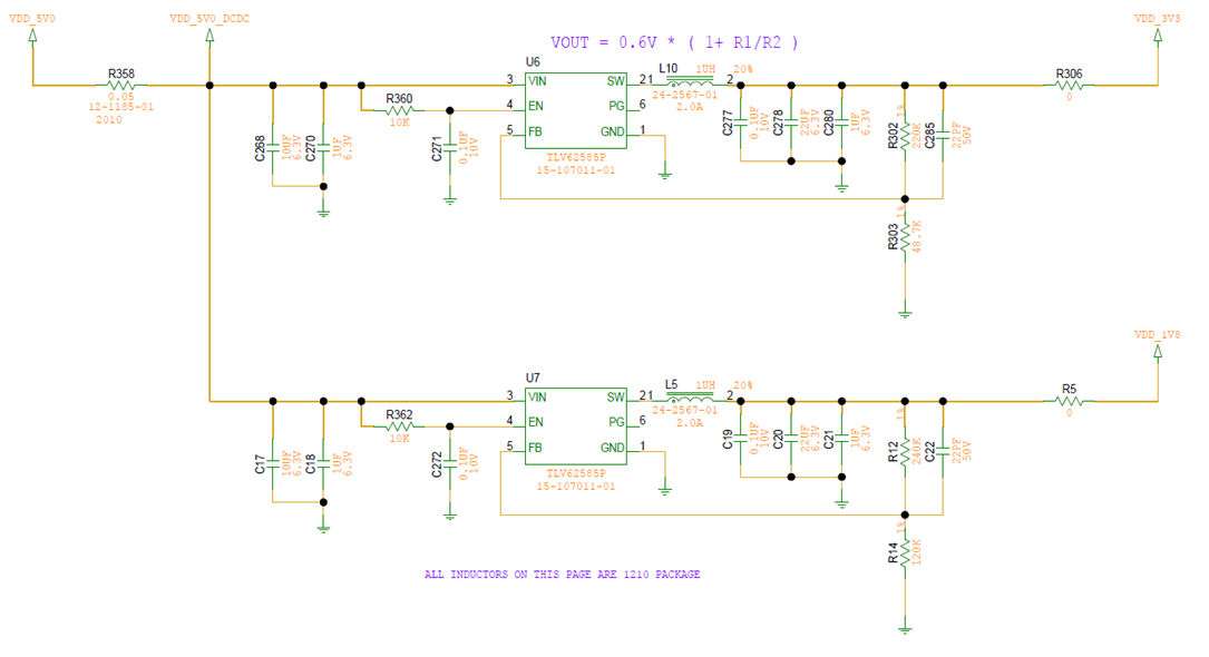
As we power on the board and test the output voltage value. The VDD_1V8 is 1.800V and it’s good but the VDD_3V3 is a little shift and the actual value is something like 3.210V. Then we test the voltage level on FB pin (Vfb). The result is like the picture shows below:
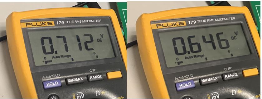
For the VDD_1V8, although its output value is correct(1.800v as measured), but its Vfb is 0.712V. And for the VDD_3V3(3.210v as measured), its Vfb is 0.646V. It’s all quiet different from the due value 0.6V as shown in datasheet:

These are the issues we encounter when testing the TLV62585. And it’s quiet weird from our perspective…since the feedback resistor is all right and the input is good. Do you have any clue and suggestions on how can we make it right?
