This thread has been locked.

If you have a related question, please click the "Ask a related question" button in the top right corner. The newly created question will be automatically linked to this question.

LM2611: LM2611: instability

Part Number: LM2611

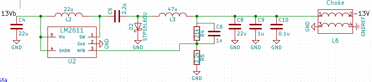
I'm noticing some very odd behavior with my design for the LM2611. I'll give you some quick specs:

L1: 22 uH

L2: 47 uH

Cin: 22 uF

Cout: 23.1 uF (three caps, one 22 uF, one 1 uF, and one 0.1 uF)

Ccuk: 2.2 uF

Vin: 13 V - 13.9 V

Vout: -13.5 V

Iout: 1 A

The power structure of this project is a bit complicated. There are a lot of different power rails for different purposes. Vin is 18 V, which solely supplies a switching buck converter which powers this regulator (and several others).

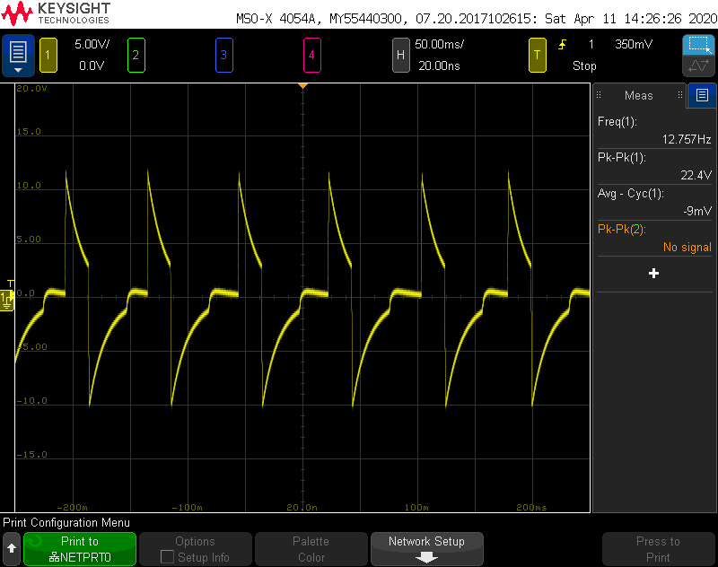
The first thing I noticed is that the switching freqency is very low. With no load, it's only 500 Hz. As you increase the load, the switching frequency increases. One of the inductors rings, so it's well within the audible range. When the load is greater than about 600 mA, the waveform at the output is radically different. You can see the waveform below. Obviously this is not how the regulator is supposed to work. Note that the frequency is only 32 Hz, and Vp-p is 15.2 V!

When the load is around 550 mA, the regulator erratically switches between this, and the expected waveform.

Does anyone have any idea what is going on here?

Thank you!

  • Hi Alexander,

    Thanks for reaching out.

    1. Could you please post the whole schematic, and the PCB layout? If it is sensitive, you can send it to me via private message.
    2. What diode are you using, is it rated for at least 40 V?

    Best regards,
    Milos


  • Hi Milos,

    The diode I'm using is a STPS5L60U, and it's rated to 60 V. One quick update, there was a 100 uF capacitor at the output that I thought I had removed before posting this message. I have since removed it, and that sorted out the switching freqency issue somewhat. It's now switching at about 25 kHz. Also, the feedback resistors, R4 and R5 are 68 kO and 7.5 kO respectively. I didn't have 21 kO resistors on hand, and these yeilded the closest match. This would make Vout 12.4 V. I am still experiencing instability at loads greater than 600 mA. I've attached the schematic and PCB layout. Ignore C7, it's the 100 uF cap I removed. I've also attached a new screeshot from my oscilloscope with the output waveform at 600 mA. It's different, although not substantially. As you can see, it's switching at 12 Hz.

    Oscilloscope screenshot

    Schematic

    Front side without the planes filled

    Front side with the planes filled. Note that the front side is the ground plane(s).

    Back side without the planes filled.

    Back side with the planes filled. Note that the back side has the power planes.

    Thank you!

  • Hi Alexander,

    Thanks you for the additional info, I will look into it by the end of the day.

    Best regards,
    Milos

  • Hi Alexander,

    Thank you for waiting.

    Checking again you operating conditions, At Vin = 13 V, Vout = -13 V, the device cannot support such a high output current. Please refer to Figure 22 of the datasheet. It shows that the maximum output current for Vin = 12 V, Vout = -12 V (which is close to your conditions) is typically 400 mA. You can also use equation 6 in section 7.3.3 of the datasheet to estimate the maximum output current that you can expect. For your conditions it is around 500 mA. If you go above that, the converter will lose regulation as the duty cycle is limited by the switch current limit. The device might cycle through on/off phases, which is what you see on the scope (which by the way is not the switching frequency)

    As for the layout, please try to follow the recommended layout from the datasheet more closely, or take look at our LM2611EVM. The components around the converter should  be placed as close as possible to the converter, otherwise you might have EMI issues or reduced efficiency.

    Best regards,
    Milos

  • Hi Milos,

    I was looking at those figures and wondered if I was over driving the chip. I can't very well decrease Vout, so I'll either have to revise the current requirements for the project or design an inverting converter myself. Thank you for your help, you answer was very clear!

  • Hi Alexander,

    Alternatively, you might consider one of our inverting modules:
    http://www.ti.com/power-management/non-isolated-dc-dc-switching-regulators/buck-boost-inverting/buck-boost-inverting-modules-integrated-inductor/products.html

    Or using a buck converter configured as an inverter, as described in this application note:
    http://www.ti.com/lit/an/slva458b/slva458b.pdf

    Best regards,
    Milos