This thread has been locked.

If you have a related question, please click the "Ask a related question" button in the top right corner. The newly created question will be automatically linked to this question.

UC1825B-SP: Application Guide for Designing Buck Converter

Part Number: UC1825B-SP
Other Parts Discussed in Thread: UC1823A-SP, , UC1843B-SP

Hello,

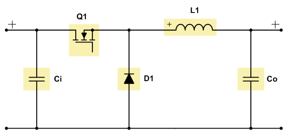
TI offers various space-rated  "PWM controllers & resonant controllers" ICs. When I look at their datasheets (for instance, for the UC1825B-SP), it says it can support a Buck topology. However, the datasheet does not have a reference circuit as to how to wire it for a Buck topology. Are there any reference or application documents I could take a look at to use any of these space-rated PWM controllers (UC1825B-SP, UC1823A-SP, etc) in a Buck configuration?

The reference document does not have to be space-specific, even a generic application note that says how to wire PWM flyback converters as Buck converters is perfectly OK. I just see that the datasheets say they can be used for that and I'd like to know how.

Thank you,

  • Hey Juan,

    If you are going to use a controller for a buck I would probably suggest using the UC1843B-SP.

    The UC1823A-SP likely works better for bucks, but doesn't have the same radiation information the UC1843B-SP has.

    As far as how it connects, The UC1843B-SP only has one output which needs to connect to the high side FET in the buck and the current sense needs to connect there as well.

    The current sense is generally done with a current sense transformer if you have dealt with those.

    Thanks,

    Daniel

  • Hello Daniel,

    Thank you for the response and how to use the UC1843B-SP as a Buck. Just two follow ups:

    1) What do you mean by "same radiation information"? It appears both of these ICs are appropriate for my application as far as I can see.

    2) Just for the sake of discussion, I would still like to know how to hook up the UC1825B-SP as a Buck converter.

    Thank you once again,

    Juan

  • Hey Juan,

    1) The UC1843B-SP has SEE and 100 krad TID data while the UC1823-SP lacks both. The UC1825B-SP is not as suited for the application (see 2)

    2) The UC1825B-SP has two outputs, but those outputs are not the same as you would want for a buck converter. A buck converter at 40% duty cycle would want one output to be 40% and one to be 60%, the UC1825B-SP would have one at 40% and the other at 40% as well. To use the UC1825B-SP as a buck, you actually only use one of the outputs which is not obvious. Since you are using only one of the outputs, the UC1843B-SP is actually easier to use.

    Thanks,

    Daniel

  • Hello Daniel,

    Thank you for your responses. They make perfect sense.

    Just to clarify, if I'm using the output of any of these ICs to drive the high-side FET (which you say is doable), do I just use a diode for the low-side FET? Or would I need additional circuitry that inverts the output of the PWM ICs and drives an actual low-side FET?

    This is why I was hoping there was some Application Note schematic. Some of these details aren't perfectly clear to me.

    Thanks,

    Juan

  • Hey Juan,

    You are correct that the bottom "FET" is a diode as shown in the below picture:

    If you were to use a FET instead you would need to have a way to invert the signal coming out of the UC1843B-SP

    Thanks,

    Daniel