This thread has been locked.

If you have a related question, please click the "Ask a related question" button in the top right corner. The newly created question will be automatically linked to this question.

TPS84621: UVLO settings 12V Input

Part Number: TPS84621

Hi all

I have TPS84621 and 12VDC Input voltage.

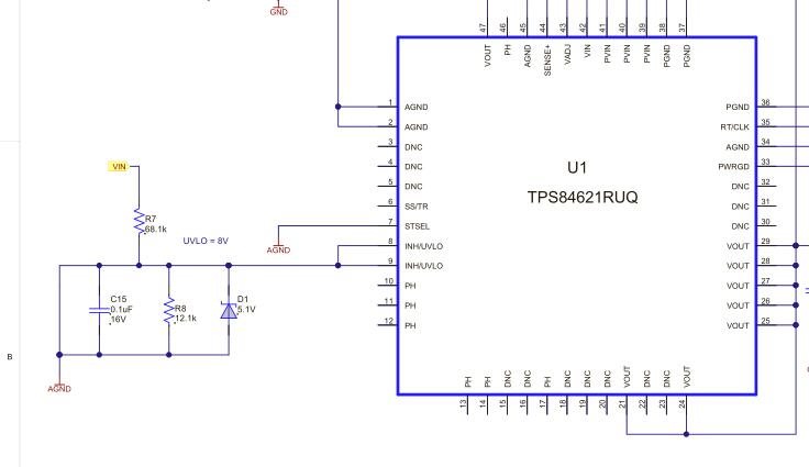
Therefor in need to put an resistor network in front of INH/UVLO input right?

In the datasheet, there is only up to 10V (Table 9)

What resistors do I need to select? (I assume it will not work when i use 8V VIN UVLO resistor settings?

There is also some reference schematic https://e2echina.ti.com/resized-image/__size/1230x0/__key/communityserver-discussions-components-files/24/dioe.jpg

but why is this GND connection to the left side of the capacitor??

  • Hi Roman,

    You only need to add a resistor divider if you want to adjust the UVLO threshold (i.e. the threshold at which the part will start normal operation and switching) to a different value than the internal VIN UVLO rising threshold of 4.5V max.

    The 8V option in the table is the resistor divider to set the rising threshold to 8V. That means as your 12V input supply rises up, the device will be enabled once the voltage reaches 8V. They hysteresis value is how far below the turn-on threshold that the input voltage must fall before the device is disabled. In this case, the hysteresis is 500mV, therefore, your input supply must fall to 7.5V before the device will be disabled.

    At what input voltage do you want the module to start normal operation?

    I am not clear on your question about the GND connection. When using the UVLO resistor divider, we recommend connecting the bottom resistor to analog GND (AGND), which is what your linked schematic shows.

    Hope that helps clarify,
    Kris

  • Hi Kris

    Ok, got it regarding the 8V.

    My problem is, that the PWRGD is toggling. (12VDC input is constant)

    So i assume there could be something wrong with the UVLO settings. (Of course it can also be other things).

    What i tried is the schematic as i posted, but without the AGND connection from from C15 "+", the left one.

    Probably this is the isue, but i am not sure what this connection do?

    Other option is maybe to remove this stuff and just let the device startup as soon there is power.

    (Just leave it open?)

    Thank you

    Roman

  • Hi Roman,

    Oh sorry about that - I didn't see that wire short! That schematic is basically showing that the INH pin is tied to AGND, which would keep the part disabled. That connection shouldn't be there. Where did you get this schematic?

    Anyway, it sounds like you do not have that in your actual design so that would not be involved in your PGOOD toggling.

    Please try removing the divider and leaving INH pin open to let the device power up based on the internal UVLO. Whether that solves the PGOOD toggling or not (I would suspect not if your 12V supply is very stable), either way we will have a clue as to where to look next.

    Kris

  • Hi Kris

    You are right, after removing the divider, the issues was still there.

    Meanwhile i was able to find the problem, it was the CLK that was not ok. Now it is working.

    Thank you for your help!!

    Regards

    Roman