Because of the holidays, TI E2E™ design support forum responses will be delayed from Dec. 25 through Jan. 2. Thank you for your patience.

This thread has been locked.

If you have a related question, please click the "Ask a related question" button in the top right corner. The newly created question will be automatically linked to this question.

LMG1020EVM-006: Questions about LMG1020 output waveform

Part Number: LMG1020EVM-006
Other Parts Discussed in Thread: LMG1020, LMK61E2EVM

Hi Colleagues,

According to customer needs, I want to use the LMG1020 to drive laser devices.

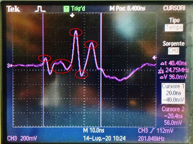
During the test, I found that when inputting a 1ns pulse width signal, the output signal of the LMG1020EVM is a strange waveform, which is not the ideal 1ns pulse width.As shown below.


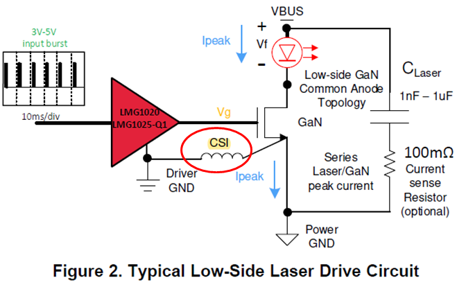
After reading 《Optimizing Gate Driver Layout for LiDAR Applications》, I found that this output waveform may be caused by the inductance(marked in yellow) in the loop.As shown below.

But the reason is not elaborated in the text, so I would like to ask how the inductance affects the output waveform in detail.

The link to 《Optimizing Gate Driver Layout for LiDAR Applications》 is as follows.

《Optimizing Gate Driver Layout for LiDAR Applications》.pdf

Best regards!

  • Hi Xinhang,

    Thanks for reaching out on lmg1020.

    Are these waveforms coming from the lmg1020 evm?

    If not, can you share the gate drive layout for review?

    Inductance can affect the waveform depending on where the inductance is coming from as well as the peak current in the system. Usually inductance slows down the edges and can create ringing like you see in the waveforms.

    Thanks,

  • Yes, this output waveform does come from the Vg position of LMG1020EVM.

    I used the probe of the oscilloscope to measure the output waveform.

    Of course, I think it is very likely that there are lead resistance, lead inductance, and stray capacitance inside the probe.

    Therefore, a standard pulse signal is prone to overshoot and ringing after passing through a long transmission line.

    Do you think this reason is reasonable?

  • Jiao,

    My name is Mamadou, I work with Jeff, can you confirm that your measurements are done through tip & barrel method? What does your measurement setup look like? (probe on EVM). 

    Can you verify your operating conditions match the EVM recommended operating conditions?

    Can you please share Input and Output waveforms on same waveforms?

    Regards,

    -Mamadou

  • Hi  Mamadou,

    After analysis, I have found out the reason.This phenomenon is mainly caused by two factors.

    1. The problem of Pulse time

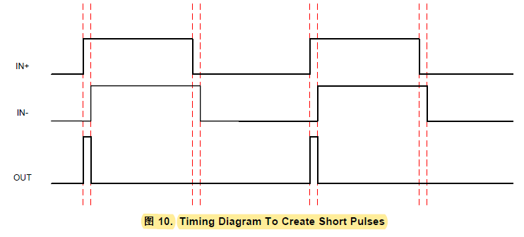
    We use LMK61E2EVM to generate a differential clock signal, and set the two input signals to maintain a phase difference of 1ns, so that in an ideal state, the output is a 1ns pulse.

    However, in fact, the output at Vg is a waveform with a pulse width of about 40ns, and the waveform is not ideal.

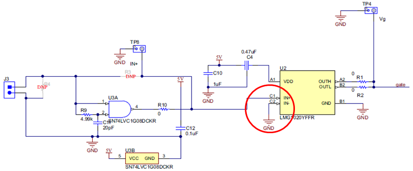
    By looking at the EVM schematic diagram, we can find that the IN- on the board is connected to GND, that is to say, the signal input from IN- is always in a low state, so when IN+ is high, there will be a phase difference. And the output waveform pulse width is the pulse width of IN+.

    2.The problem of the pulse waveform

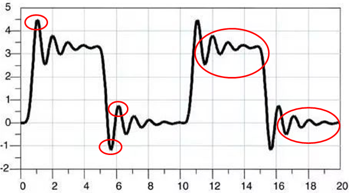
    When the signal propagates forward along the transmission line, a transient impedance will be felt at every moment. This impedance may come from the transmission line (such as an oscilloscope probe) itself, or it may be from other components in the middle or at the end. As long as the perceived impedance changes, the signal will reflect. These factors may include excessively long traces, end-matched transmission lines, excessive capacitance or inductance, and impedance mismatch. If the signal is reflected back and forth between the driver and the receiver multiple times, a ringing phenomenon will occur, which prolongs the time required for the signal to stabilize, and thus affects the stable timing of the system.

    Finally, thank you very much for answering my doubts.