This thread has been locked.

If you have a related question, please click the "Ask a related question" button in the top right corner. The newly created question will be automatically linked to this question.

BQ77915: My PCB is not work.

Part Number: BQ77915

I completed my schematic for my project: 20S 80A PCM.

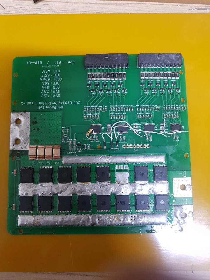
But my completed PCB does not work.

I upload my schematic for reviewing them.

Please give me how to solve this.

I already checked my missed circuit, LD for upper ICs and added to on PCB by hand wiring, but still not work for DSGfet.

Charging is work well but Discharging is not working.

Prototype v1.pdf

  • Hi,

    Please check the value of the CHG and DSG pins of each of these devices when the cell voltages are nominal. All the pins should be high. If not, use this table in the datasheet to determine which faults could be occurring:

  • Hi, Shawn.

    Thank you for your reply.

    But I can't solve this error on my PCB.

    I don't know how can I check that.

    Can you explain how to check by Oscilloscope?

    I checked all of CTRD and UV functions, but I can't interpret them Correct or not.

    Thank you. :)

  • Hi,

    Using an oscilloscope would definitely work. Section 10.2.3 has some screenshots of how the OV protection works. The pink line is the CHG pin of the device, and the green line is the DSG pin of the device. You can see that both of these values are HIGH when the device is operating normally, with no faults. Once a fault is detected (in this case cell 2 goes into over voltage), you can see the pink line go LOW. 

    It would be really helpful to replicate this procedure and make sure that the CHG and DSG pins are behaving as expected. Once OV is proven to be correct, you can go through and check the other protection thresholds.

  • Hi, Shwan.

    Thank you for your reply.

    But I can't see that image.

    I tried to fix my circuit, but still not work my circuit.

    Can you review my circuit that uploaded on this thread?

    Thank you :)

  • Hi,

    Apologies about the image! It was supposed to be figures 10-10 and 10-11 in the datasheet.

    I reviewed your schematic, and nothing appeared to be incorrect. I would recommend reviewing the applications curves in the datasheet, and the quick start guide listed in the BQ77915EVM user guide to get a better understanding of how the faults work. I would individually test out each of the faults to make sure the circuit is functioning correctly. 

  • Hi, Shawn.

    Thank you for your review.

    I solved my PCB my short to P- and BAT+

    Now, the circuit is working well but I got some other error.

    I designed for 80A discharging and charging, but when I tested my DC Load some MOSFETs are getting high temperature to point solder is melted by them.

    Attach my PCB picture.

  • Hi,

    It seems that your discharge current is very high. Please check with the battery manufacturer that this is a safe discharge current. I would recommend increasing the sense resistor to a higher value.

  • Hi.

    My test battery pack is 20S8P by LG Chem's M50T cell.

    This cell's MAX DISCHARGE CURRENT is 15A per cell.

    and my battery pack can be discharged up to 120A

    Anyway, my MOSFET's Vth is 2.9V but my lowest IC can not out DSG voltage to turn on MOSFET.

    Even I changed to the lowest IC's OCDP resister changed from 10M to 100K

    Also, I added a circuit the highest IC's PRES pin connect to VDD via 10K resistor.

    But I can't get PACK voltage even all cells right now on 3.603V, totally 71.98V

    How can I fix my PCB?

    I already added LD circuit for IC1, 2, and 3 and changed to the lowest IC's OCDP resistor.

  • Hi,

    I believe this is a duplicate thread. Please see my response here: https://e2e.ti.com/support/power-management/f/196/t/926225