This thread has been locked.

If you have a related question, please click the "Ask a related question" button in the top right corner. The newly created question will be automatically linked to this question.

BQ27621-G1: Gauge returns non-sense values

Part Number: BQ27621-G1
Other Parts Discussed in Thread: BQ24014, BQSTUDIO, EV2400, TMS320C5515
Hi,
First of, let me tell you about specs and register settings. We are trying to use the gauge with Varta EZPack XL Li-Po Battery
Voltage: 3.7v
Capacity: 2400mAh
Max Charge Voltage: 4.2v
Charge cut-off: 23mA or timer 3.5h
Discharge cut-off: 3V
Following the TRM and the Quick Guide, we did the following changes
Design Capacity: 2400mAh
Design Energy: 8880 mWh
Terminate Voltage: 3100mV
Taper Rate: 600 (which corresponds to 40mA)
Taper Voltage: 4200mV
Design Voltage: 3700mV
Chem_ID: The default value 0x1202 is used since it is said to be for batteries with 4.2V charging voltage.So this is not changed. 
Op_Config: 0x94D8 
   [BIE] bit is cleared. The BIN pin is grounded with a 10kOhm resistor. Host sends a BatteryInsert Command. 
   [BAT_DET] bits in Flags is checked and confirmed that it is set.
We did not experience any problems writing these values to the corresponding registers.[INITCOMP] bit in the CONTROL_STATUS is also confirmed
to be set. 
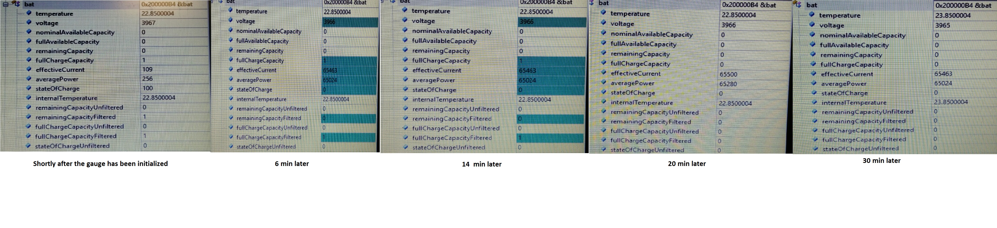
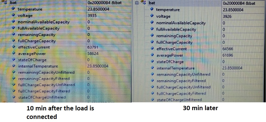
After all these settings, when we have read values, only Voltage and Temperature values seem to be correct. Under normal conditions our application draws around 15mA.
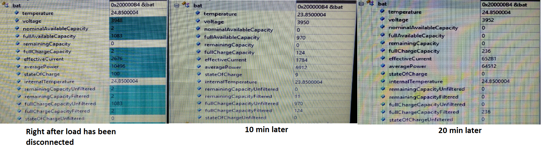
When it does so, SOC is read to be 100. As soon as we increase the load to 70mA SOC goes to 0 and stays at 0 as long as the load is connected. When we 
disconnect the load it either goes back to 100 directly or gradually goes some numbers (100 or some other numbers). This repeats every time we connect the load.
Effective current value never made sense at all.The only correct thing about it is its sign. The value is non-sense.
I am not mentioning other values because they are 0 or non-sense values. 
While trying to fix these, We noticed that the [DSG] bit is never set. As long as we understood, our load current was below the Discharge Current Rate Threshold and we thought that this could be the problem. 
So we updated the following thresholds too
Dsg Current Rate Threshold: 500 (which corresponds to 48mA)
Quit Current Rate: 1000 (which corresponds to 24mA)
I also want to express that we are using BQ24014 as the charger, if it helps to know at all. We used exactly the same set up (same gauge, charger and battery) on another board which was drawing around 150mA. Interestingly
on that board it worked at the first trial very well. However on our new board it does not work. The only difference is the current, which we believe is taken care of by changing the thresholds.
We will be more than happy if you can please give us some hints about what could be wrong here and how it can be fixed. If the need be, please suggest other gauges as well
(if you are sure it will work). However please note that, it has to work with both 2400mAh (single cell) and 4700mAh (1S2P) batteries. 
Best,
Denn
  • The new lines disappeared somehow. Sorry about that..

  • Hello Denn,

    So the only difference between the two setups you tested is that the current is lower and when you increase the load of the first test SOC jumps, but it didn't before? Everything else remained the same?

    Do you have an EVM that you could use to log the discharge with an EV2400 and bqStudio? Or is this all embedded? Using an EVM will let us debug the system quicker if we have the data from the discharge.

    What data are you pulling currently? Do you have a log of it that you can share?

    Sincerely,

    Wyatt Keller

  • Hi Wyatt,

    Thank you very much for your concern.

    I think I have to make the difference between the two setups clearer. Both setups acquire the same data using the same sensor. Power stage is exactly the same for both. The only difference is that, the older one was using a WiFi module to transmit the data, and TMS320C5515 as the controller, the new one uses a BLE module both as the transmitter and the controller, thus the current consumption is a lot less. However as I said, the power stage for both boards, including the all regulators, gauge, charger and battery, is exactly the same. The older card was consuming around 150mA, and the new one consumes, under normal conditions (unless we do not connect an external load to increase the current), around 15mA. When the external load is connected a total of around 80mA is drawn. Also note that, the external load is just for test purposes, in the regular application there will not be such a load. We just wanted to see how gauge behaves under a bigger load and to try to catch a hint regarding what the problem is. 

    We are only transmitting the SOC value and it made sense all the time in the old board. We did not have problems with it and do not remember having problems with the other values. However, we did not pay much attention to them to be honest.

    Unfortunately, we do not have an EVM, both of the cards mentioned above are custom design embedded cards. 

    I have organized some results for your consideration. Please have a look at them.

    Results after the initialization of the gauge, with no external load. So only 15mA is drawn here.

    The external load is connected around 80mA is drawn

    When the external load is disconnected

    What we observed is that after the load is connected, SOC value can be 100 or something else. It moves around for a while, however if we wait long enough it goes to 0 at the end. 

    We hope these will give some hints about what is wrong here.

    Best,

    Denn

  • One more input before you answer; we have noticed that the gauge cannot be sealed for some reason. The SEALED command is sent, however the SS bit CONTROL_STATUS is never set. We noticed we have not sealed it on the old board. I am not sure if this is related to the problem we are having but please take this into consideration as well. What could be the possible reasons of not being able to seal it?

  • Hello Denn,

    It looks like there is some kind of error happening with the current reading, have you tried checking the connections on your board to see if they are correct or if there's a short on the SRP or SRN pins that would cause it to max the current ADC?

    Can you log this data over time so we can see what is happening while the SOC is jumping? If you could log the control_status, Flags, and operation_config we can debug more efficiently.

    Sealing the device most likely isn't related to the SOC jumps, what commands do you send to seal the device?

    Sincerely,

    Wyatt Keller

  • Hi Wyatt,

    We also thought the possibility of short and open contacts. This is what we came up with. Please feel free to warn if our reasoning is incorrect. The gauge has;

    -Two I2C pins which work fine,

    -BIN pin should be fine since we are able to control BAT_DET

    -BAT and VSS pins should be fine since the voltage reading is perfectly fine

    -We toggled GPIO pin but will check it again.

    -VDD output is 1.8V

    This gauge does not have sense resistor so there no SRN and SRP pins.

    To seal the gauge we send 0x0020 to address 0x00. We are able to use other subcommands successfully such as DEVICE_TYPE, SOFT_RESET, SET_CFGUPDATE..

    I will try to share the logs you have asked for.

    Is this gauge suppose to work with 15mA? Do you think it will be easier to work with a gauge that has a sense resistor?

    Best,

    Denn

  • Hello Denn,

    You will need to make sure that there is no noise and the voltage on the voltage sense pin is clean to make sure the gauge calculates the current correctly from the voltage and OCV table.

    Let me know when you collect the logs to analyze.

    Sincerely,

    Wyatt Keller

  • Hello Wyatt,

    Before I talk about the logs, let me tell you about a mistake we had made in the pcb design. We have skipped the "Kelvin Connection" that was told in the datasheet. This is newly noticed. To fix it in the best way possible, we have soldered BAT+ to the pad of the capacitor connected to the BAT pin via a jumper cable. In terms of the connection it is now similar to a Kelvin Connection. 

    The logs you have asked for were collected after this correction. You will find 2 different logs (in both excel and txt formats for your convenience).

    LOG1: We configured the gauge let it run until the sample# 152 (please note that period between two samples is 5secs). Until this sample only around 15mA was drawn. After this sample the external load was connected and around 80mA was drawn all the way to sample# 12213 and then we disconnected the load till the end. 

    LOG2: Again we configured the gauge,

    sample# 0 - 130 without load

    sample #130 to 290 with the load.

    sample# 290 to 420 without load

    sample #420 to 665 with the load.

    sample# 665 to 875 without load

    sample# 875 to 1001 with load..

    sample# 1001 and on without load

    Please do comment on the Kelvin Connection problem. I hope the logs can give some hints about what's wrong either hw or fw. Many thanks in advanced. Looking forward to hearing from you.

    Best,

    Denn

    gauge log1.txtgauge log1.xlsxgauge log2.txtgauge log2.xlsx

  • Hello Denn,

    The gauge will read back a signed number, it looks like you are reading that value as an unsigned integer. I think if you switch how your tool reads from the gauge it will fix this problem and give you a negative effective current instead of reading over 65,000 on the discharge.

    I would also make sure to follow the layout guidelines in the datasheet to minimize noise.

    Sincerely,

    Wyatt Keller

  • Hello Wyatt,

    We know gauge returns two's complement for effective current and average power. We interpret them accordingly. However the logs show the raw data. Fixing this on the logs does change the raw SOC value that gauge returns as you will agree. Moreover, it is the converted effective current values that do not make sense. Also SOC is the main problem. Are you able to  figure out anything else from the logs?

    In our next PCB we will correct the layout mistake. For now the aforementioned solution seems to be the best available one.

    Would you have any other suggestions for us please?

    Best

    Denn

  • Hello Denn,

    I see the issue you face is more with the SOC. Have you gone through the configuration of the gauge by setting the best fitting chem ID and design capacity? It looks like all the values used to calculate SOC are jumping as well and they are originally tied to the programmed values.

    The quick start guide explains all the parameters you need to setup: https://www.ti.com/lit/ug/sluuap5a/sluuap5a.pdf?ts=1596119992130&ref_url=https%253A%252F%252Fwww.ti.com%252Fproduct%252FBQ27621-G1

    Sincerely,

    Wyatt Keller

  • Hello Wyatt,

    Regarding the configurations, please be referred to my very first post. Do you see anything wrong with them?

    Best,

    Denn

  • Hello Denn,

    You will need to change your dsg 1 rate threshold so the gauge enters discharge mode during your normal current draw, so less than 15mA. It looks like currently the gauge never enters discharge mode and doesn't calculate SOC accurately because it does not know it should be actively calculating it.

    When you switch capacities do you also reprogram the design capacity as well? 

    Sincerely,

    Wyatt Keller

  • Hello Wyatt,

    We are not changing the Dsg Current Threshold back and forth once it is set to 24mA. Design Capacity is not changed either. Once it set to 2400mAh, it stays as it is.

    However, we now have two concerns;

    1)Correct us if we are wrong but as far as we understood from the datasheet "the absolute value of Quit I Rate" (which can be set to a minimum of 24mA) has be to smaller than the "the absolute value of the Dsg Current Threshold" (which is to be set to 15mA). Does it not?

    2)The minimum value the Dsg Current Threshold can be set to is 12mA. If we want a gauge that will correctly work when the board draws even less than 12-15mA, should we go for another gauge?

    Best,

    Denn

  • Hello Denn,

    Switching capacities may also affect the gauging, it would be best to keep the capacity which is programmed in the gauge.

    Yes you are correct, your application may be hard to implement using this gauge. The current correlation from voltage works better at higher current values so there's more resolution.

    You can review other gauges for your application: https://www.ti.com/power-management/battery-management/fuel-gauges/products.html#p1152=Single%20Cell&p338=Li-Ion/Li-Polymer&p1960=System

    Sincerely,

    Wyatt Keller

  • Hello Wyatt,

    What kind of gauge should we use for such an application? Would you please suggest us couple of gauges?

    Best

    Denn

  • Hello Denn,

    I would suggest you find a gauge with similar functions but using a sense resistor to gauge the current more accurately.

    The BQ27426 is similar ROM based gauge, so it has no NVM flash memory and needs to be reloaded after going through a POR.

    The BQ27520-G4 has an integrated LDO and has dataflash so it will have any configurations if a POR occurs.

    Sincerely,

    Wyatt Keller