This thread has been locked.

If you have a related question, please click the "Ask a related question" button in the top right corner. The newly created question will be automatically linked to this question.

LMZ14203H: Malfunction on batteries

Part Number: LMZ14203H

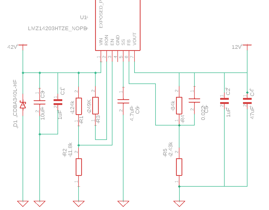
For a voltage step-down project that accepts an input range from 28 Volts to 42 Volts I decided to use the LMZ14203H component. Respecting the design for our use :

- 28-42 V input
- 12 V 3A output

We observe no problems on stabilized power supply, on the other hand when we want to connect our pcb with the LMZ14203H component to the batteries the component fails. After investigations I decided to protect the circuit with a TVS diode (CDBA340L-HF) to clamp an overvoltage coming from the batteries. Even with this extra protection the design is fails again. Could this be due to the capacity, 10uF, VIN too low ?

  • Hi Nicolas,

    Before I provide you with some of our conclusions, can you please tell me a little bit more about this battery application?

    When testing with the battery attached, are you performing a hot-swap? If so, that is where some of our concerns fall under. I am not sure if the diode in your circuitry is reacting fast enough to prevent an in-rush current. I would highly recommend to place an electrolytic bulk capacitor with a high ESR at the input to dampen any of the noise.

    Aside from that, I would like to point out two areas of concern:

    1. After reviewing the schematic provided, we noticed that the UVLO threshold is relatively low. For battery applications, we recommend to set the threshold closest to the lowest VIN to preserve the battery voltage.
    2. It looks like you are operating at the absolute maximum range. Please make sure to stay within the range as operating above the recommended can over stress the part.

    Regards,
    Alejandro

  • Thank you for your prompt response!

    Of course, we use a battery that is switched off via MOSFET controlled by a button so normally no worries about hot-swap.
    Its operating range is between 28 volts and 42 volts at its max.

    I will try to test with an electrolytic capacity at the input of the system !

    For the ULVO it is only concerned by the "EN" pin, right ? I have to use this equation to get closer to 28 volts :

    RENT / RENB = (VIN-ENABLE/ 1.18 V) - 1

    I will also follow your recommendations and see if we don't have batteries with higher voltage levels but normally this is not the case.

    Thank you very much Alejandro I come back to you after my first tries.

  • Correct, use the equation you provided found in page 17 of the datasheet.

  • Hello Alejandro, we have added an electrolytic capacitor to do some tests for the moment everything is going well, the capacitor is doing its job well! I'm still waiting for a few more tests to validate the new design and close the post. Thanks for the tips of this design! 

  • That's great news. We will wait on your updates patiently.

    Kind regards,
    Alejandro

  • Hello Alejandro !

    Well, after a few days of testing everything seems to go well ! I think that for the moment we can say that the subject is solved. If there is the slightest problem I will come back with more details. Thanks again Alejandro!
    Bye!