This thread has been locked.

If you have a related question, please click the "Ask a related question" button in the top right corner. The newly created question will be automatically linked to this question.

TLV62585: output noise

Part Number: TLV62585
Other Parts Discussed in Thread: TPS62826

Hi Sir,

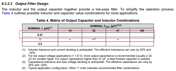
In my knowledge , L value should change to the bigger one , but the result shows change to smaller one is correct.

Could you give me some advices?
If your thought is same as my test result , please teach me the fundamental.

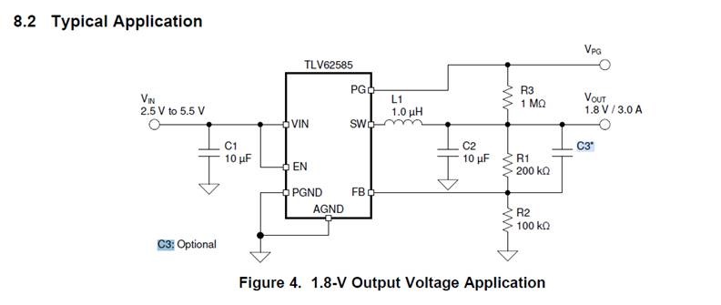
please kindly let us know if there any risk, if the inductor 1u change to 0.47u.

Test purpose:

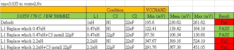
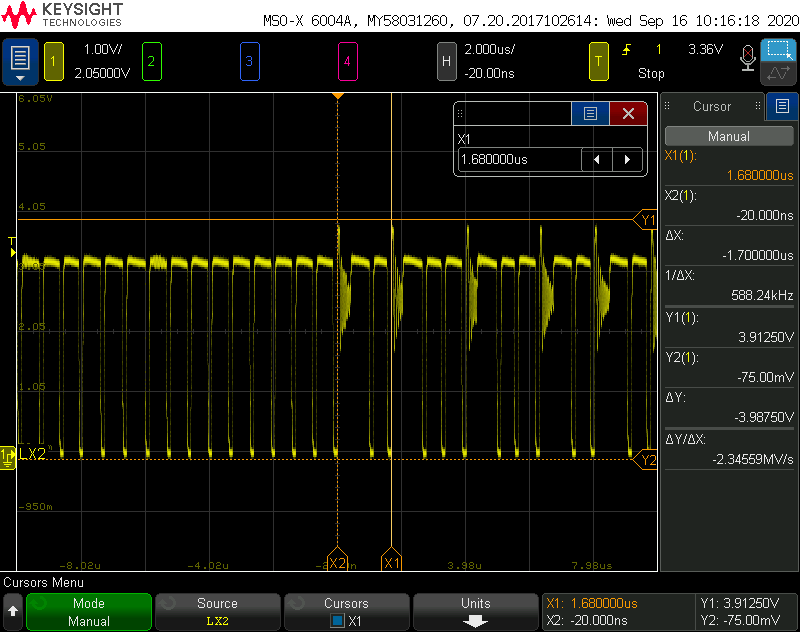
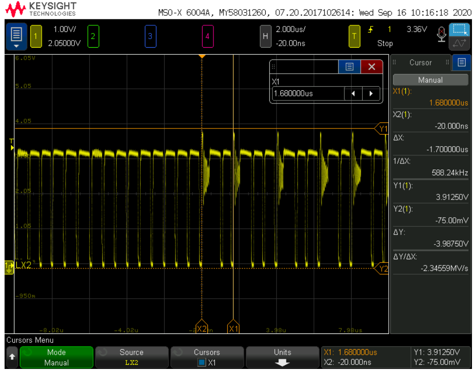
At low input voltage(3.036V)
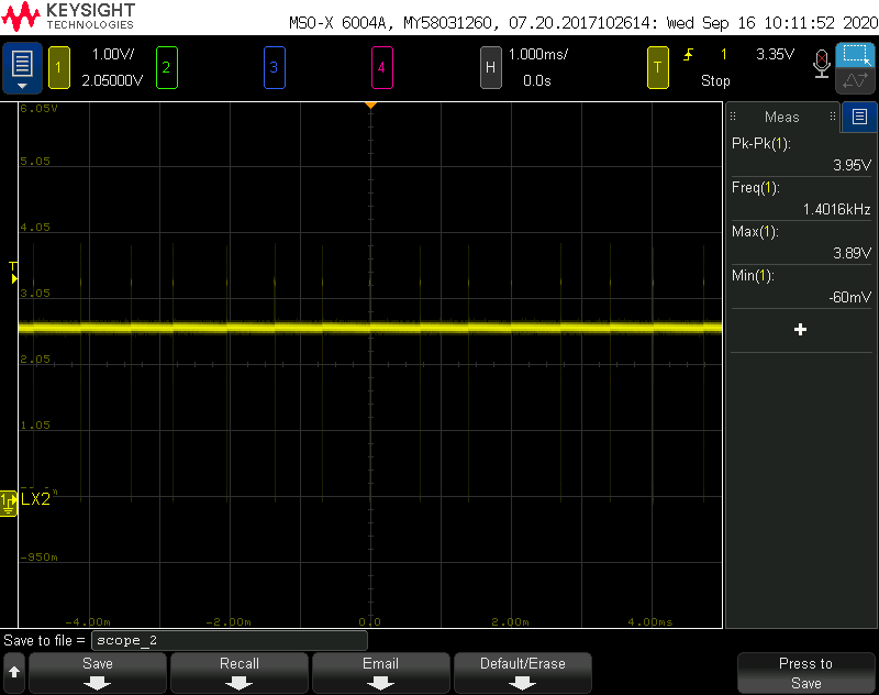
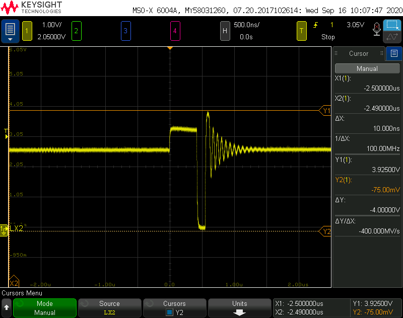
Change L1 & C3 then test the output Vp-p , target to lower than 156mV.
But we found the effect of 0.47uH is better than 2.2uH , this result is different to my knowledge.

in the current mode of TLV62585, the inductor value reduce, can the output ripple be reduced?

f your thought is same as my test result , please teach me the fundamental.

If your thought is different as my test result , maybe I have to do extra test.

  • Hi Tommy,

    Thanks for the data! Your comments on the below question give a better understanding.

    Are the measurements done for output ripple as min-max value quite confusing? Because transient would not be good with higher inductance. Did you do measurements on the same schematic and on EVM? and can you share waveforms?

    Best regards,

    Tanvee

  • Hi Tanvee,

    thanks for you reply,i know it must be to see peak to peak.

    in the current mode of TLV62585, the inductor value reduce, can the output ripple be reduced? <== i confuse by this mean, is this correct?

    we measure on same schematic and on EVM board,please kindly wait for one moment.

  • Hi Tanvv,

    due customer already do test result on their main board, think it has same result in EVB.

    whether it can really reduce output ripple if change L from 1u to 0.47uH.

    please kindly help comment about if any concern for change 1u to 0.47u, does this design has risk.

    could you help specific explanation?

    because the specification have recommend this value.

  • Hi Tommy,

    I will now takeover your queries.

    The customer observation on the decrease of ripple voltage when the inductor was changed from 1.0uH to 0.47uH is correct. At PFM mode, the device operates at peak current control and with a 0.47uH inductor where the Ton (on time) is almost half only with 1.0uH inductor. Hence, the amount of time to charge the output capacitor is also reduced to half (L = 0.47uH). To compensate for the charging time of the output capacitor and maintain the output regulation, the switching frequency will increase, which results to lower output ripple. See the figure below for reference.

    With regards to concern of using 0.47uH inductor, customer needs to verify the loop stability (phase margin should be >45 deg.) and if it meets there requirements (ex. transient load, etc.). Because this inductor was not verified and characterize, it is the customer responsibility to ensure it will work in there application.

    You can also recommend TPS62826 which offers better ripple voltage at PFM and it also uses 0.47uH inductor.

    Best regards,

    Excel

  • Hi Sir,

    thanks for your reply and let us learn this know-how.

  • Hi Sir,

    sorry~the customer has some question below and want to understand.

    1. What definition for heavy load PWM mode.( > ??  mA)   ,   What definition for light load PFM mode.( < ?? mA)?
    2. As you said , change 1.0uH to 0.47uH is correct to reduce ripple , does it means no matter what it works in PWM mode and PFM mode ?
    3. From datasheet point of view , L can be 0.47/1/2.2 uH , that means TI guarantee these L values can work at normal user application , doesn’t it?  Why TI think we have responsibility to ensure it will work in our application ? any concern?
    4. Except the output current factor , what’s the application TI will advise to modify L value ? (as I know , customer will change L due to consider about frequency response cut off point)

    could you let us learn again, look forward to you reply.

  • Hello Tommy,

    Please see comments below as highlighted.

    1. What definition for heavy load PWM mode.( > ??  mA) --> Inductor is at CCM mode,   What definition for light load PFM mode.( < ?? mA)? --> Inductor is at DCM mode
    2. As you said , change 1.0uH to 0.47uH is correct to reduce ripple , does it means no matter what it works in PWM mode and PFM mode ? --> The lower ripple is only applicable at PFM mode with 0.47uH inductor.
    3. From datasheet point of view , L can be 0.47/1/2.2 uH , that means TI guarantee these L values can work at normal user application , doesn’t it?  --> Only the 1.0uH inductor was characterized and validated. If customer intend to use 0.47uH or 2.2uH, then it is their responsibility to validate in their application. Why TI think we have responsibility to ensure it will work in our application ? any concern? --> Full design and bench validation was only conducted at 1.0uH because this value should cater most of the applications.
    4. Except the output current factor , what’s the application TI will advise to modify L value ? (as I know , customer will change L due to consider about frequency response cut off point). --> As I mentioned previously, customer needs to check the loop stability (PM => 45 deg) and the transient response as well.

    Best regards,

    Excel

  • Hi Tommy,

    If you don't have further queries, then I will close this thread. Feel free to post your comments/questions if still encounter concerns with this device.

    Best regards,

    Excel

  • Hi Sir,

    cusotmer hope can to know below question and from you learn again, thank for your great help.

    1. Please refer the LX(TLV62585 output before L) waveform I measured.
    2. In light load  , it seems operate in PFM mode right?
    3. In Heavy load , it seems it will switch PWM/PFM mode quickly. (datasheet also describe it will change to PWM mode in heavy load)
    4. In PWM mode , why output transient Vp-p also reduced when we changed L to 0.47uH , could you describe more detail ? or have any relevant application note.thanks. 

    light load:

    heavy load:

    zoom in:

  • Hi Tommy,

    1. Please refer the LX(TLV62585 output before L) waveform I measured.
    2. In light load  , it seems operate in PFM mode right? --> Correct.
    3. In Heavy load , it seems it will switch PWM/PFM mode quickly. (datasheet also describe it will change to PWM mode in heavy load) --> The device is expected to operate between PFM/PWM when the load current is in the boundary between PFM and PWM modes. But once the load is increased further then it will be purely PWM mode operation. What is the load condition below?

    4. In PWM mode , why output transient Vp-p also reduced when we changed L to 0.47uH , could you describe more detail ? or have any relevant application note.thanks. --> Do you mean the Vp-p was reduced when L = 0.47uH during transient load? Yes, this also expected because the loop response is faster with lower inductor value (the inductor current will be able to reach the required load current quicker because of faster slew rate) which resulted to lower voltage droop during step load. There is no dedicated app note to describe this behavior.


    Best regards,

    Excel

  • Hi Tommy,

    Any update on my queries on the my last post?

    Thank you.

    Best regards,

    Excel

  • Hi Tommy,

    Do you still have additional queries? If not, then I will close this thread.

    Thank you.

    Best regards,

    Excel