This thread has been locked.

If you have a related question, please click the "Ask a related question" button in the top right corner. The newly created question will be automatically linked to this question.

TPS65133: voltage overshoot at Vpos

Part Number: TPS65133

Dear TI Team,

while testing our current prototypes, some electrical components on our PCBs got damaged in consequence of volatile power supply voltage (slightly moving lithium ion battery in the device case)

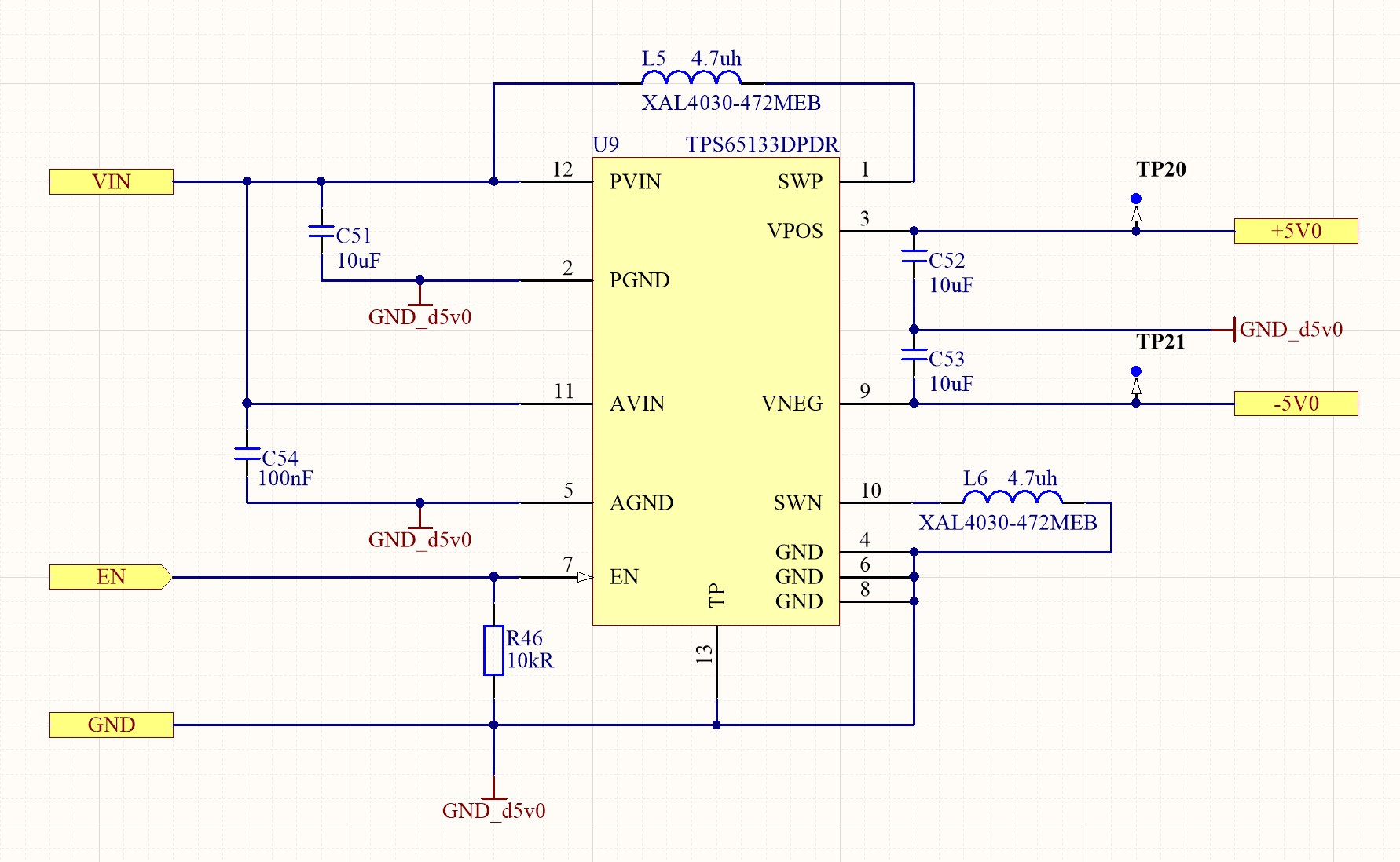
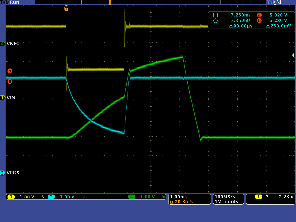
The destroyed (analog) hardware components are powered by the +-5V power rail. This power rail is built up by the TPS65133. This event is reproduceable by switching the Power supply on and off randomly in fast combinations. Please find the oscilloscope print in attachment.

-          Vbat (green) = is our main power supply and input for TPS65133

-          3V3 (yellow) = is the logic supply (e.g. the MCU which enables the TPS65133)

-          V5v0P (red) = is the positive output of the TPS65133

-          V5v0N (blue) = is the negative output of the TPS65133

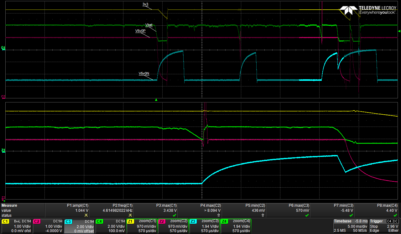
You see that the positive output (red line) of TPS65133 reach 8V and more. This destroyed some components.

The negative output looks good, because of the constant Off-Time Control.

What do you think about?

Best regards Martin.

  • Hello Martin,

    The overshoot at positive voltage rail definitely abnormal. Can you please attach your schematics and I will review to see if I can spot something that could be causing this issue?

    Kind Regards,

    Liaqat

  • Hi Liaqat,

    thanks for reply. Uploading the schematic is no problem, it is pretty the same to the datasheet. Please find the schematic in attachment.

    More Information:

    • all our current PCBs have that problem
    • It happens, with load and without
    • After some time, switching the Power supply on and off randomly in fast combination destroyed also the TPS65133.

    Best regards Martin.

  • Hi Martin,

    I don't see anything wrong with this simple schematics and at this time,  I am not sure what is causing the significant output voltage overshoot like that. The only thing remaining is perhaps some board level layout sensitivity but it is hard to say. I am not sure if this is an option for you but I will be happy to check this in my lab and try to debug this further. Please let me know if you would like to proceed with shipping your board to me.

    Kind Regards,

    Liaqat

  • Dear Liaqat,

    thanks for your offer. At the moment, I don’t want to send you one of my PCBs.

    Is it possible that you test my case with an TPS65133EVM-699? I don’t have one.

    Kind regards,

    Martin

  • Hi Martin,

    I do not anticipate this kind of problem on the EVM but to make sure, I have just ordered an EVM. My order placement said that it will take 5 business days for me to receive this EVM and I will test as soon as I receive it.

    Kind Regards,

    Liaqat

  • Hi Liaqat,

    many Thanks. I'm looking forward to the result.

    Kind Regards,

    Martin

  • Thank you and I will let you know the results of testing once I receive the EVM.

    Kind Regards,

    Liaqat

  • Hi Martin,

    I got the EVM and did some bench measurements to try to duplicate the overshoot on positive rail that you are seeing but I am not able to reproduce this overshoot. I tried both by manually quickly turning off/on the input supply to TPS65133 and than also by using a modulated power supply that can repeatedly drop the input supply to TPS65133 but I was not able to re-create the overshoot that you are seeing. My measured overshoot on the EVM is around 260mv only. So at this point, I am not sure what is causing the overshoot in your application. I think it will be cumbersome to try to debug this further via this e2e forum. If you would like to pursue further debug, please send me a private message on e2e with your e-mail address and we can connect directly via e-mail.

    Kind Regards,

    Liaqat

  • Hello Liaqat,

    thanks for your results. Can you please try to reproduce the following case and send me your oscilloscope capture?

    Extracting from my screen capture, could you please change the setup of your modulated power supply to:

    Vin = 4V
    toff <= 280µs (long enough, so that the Vpos drops and short enough that Vpos did not reduced over 900mV)

    The difference could be, that your toff >= 2ms is too long. In this time the discharge function of TPS65133 reduce the Vpos from 5V to 2.2V.

    I'm also wondering about your Vin overshoots.

    I agree, for further debugging, we can switch to private messages till we found the reason.

    Thanks and kind regards,

    Martin.

  • Hi Martin,

    Since we are further debugging this via direct e-mail, I am closing this thread.

    Kind Regards,

    Liaqat