This thread has been locked.

If you have a related question, please click the "Ask a related question" button in the top right corner. The newly created question will be automatically linked to this question.

TPS54386: Internal compensation

Part Number: TPS54386

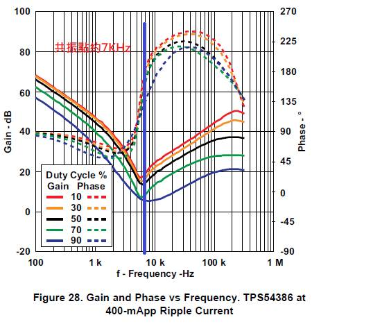
There is an internal compensation in the IC for control loop. 

In the calculation example of the datasheet, it seems it doesn't take DC bias of the capacitor into account, correct?

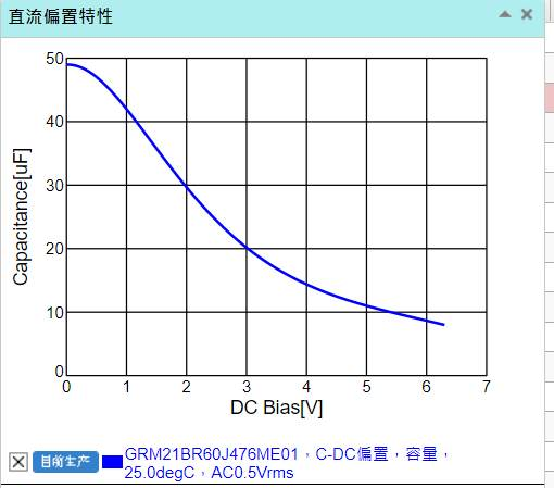
As to the MLCC capacitor material, there is a Typical Characteristics as Capacitance (uF) vs. DC Bias(V). We're wondering to know if it can also lead to the compensation adjustment? Why you didn't take it into account? Very thanks. 

  • The datasheet example I found is using a cheap electrolytic cap EEEFC1A101P.   DC bias is not as extreme in electrolytic as the ceramic.

    If you are using ceramic capacitors, use the derated value in the equation. 

  • Very Thanks. 

    However, On the TPS54386EVM board, all of the capacitors are using MLCC type. and its phase margin looks ok. I'm wondering to know if it has used the derated value for these MLCC capacitors or not?

    In the TPS54386EVM, the calculated resonant frequency is 6.8KHz with Inductor:8.2uH, Cout= 57uF (47uF + 10uF + 10uF). 

    When these capacitor using derated values with 5V, the Cout will be changed to 40uF (20uF + 5uF + 5uF) from 57uF, the resonant frequency is about 10KHz. it looks it's already over datasheet's suggestion. Could you help to clarify this? thanks.


  • I do not see the dc bias derating explicitly stated in regards to the Cout.  

    But when closing the loop, calculation precision is not mandatory for a stable loop.

    The design example on page 22 in section 8.3.12.2 of datasheet, calculates 10.9uH but uses 10uH.

    Further in the design process, states when calculating the Cout, "Any frequency within an octave of the peak may be used

    in calculating the capacitor value. In this example, 6 kHz is used".   So, 1/2 to 2 times the Fres can be used to calculate

    Cout in equation 12 which obfuscates the dc derating.   I would recommend using the derated value in the equations. 

    Figure 24 to 29 in the datasheet are the frequency response of the internal compensation (Output-to-Vc signal path).