Hi all,
We are testing TPS63050 chipset on my PCB, I have one question about customized circuit;
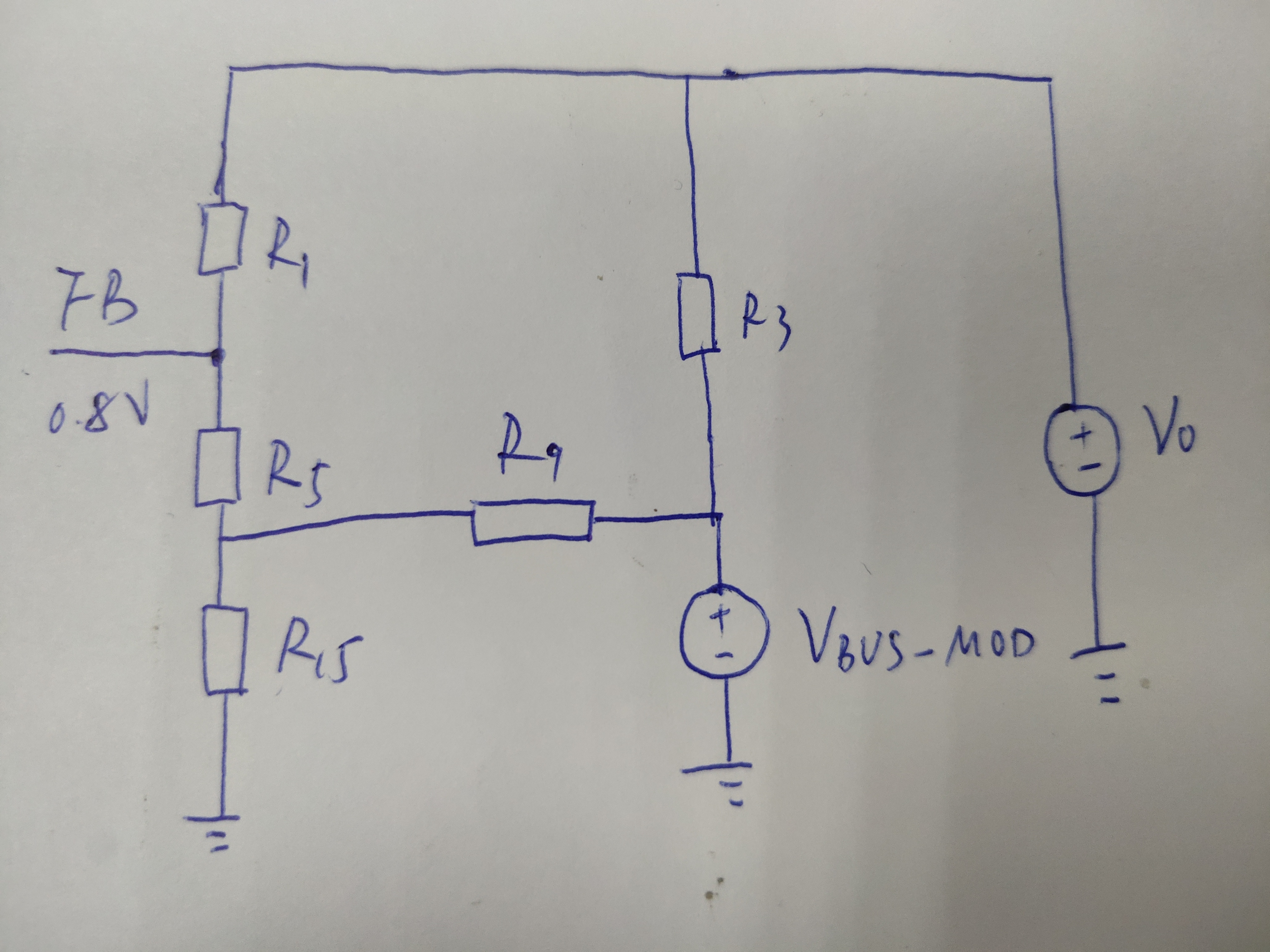
my partner gave us the schematics as below, to control VBUS voltage in three ways;

- PG pin is directly connected to MCU.
- VIN is connected to Li-ion battery that has 3.7V nominal voltage.
- VBUS_MOD is directly connected to MCU, we can make VBUS_MOD to 2.8V(MCU high output) or 0V(MCU low output)
We tested this PCB, and the result is as below;
apply voltage to VBUS_MOD=0V --> VBUS=4.1V
apply voltage to VBUS_MOD=2.8V --> VBUS=0.5V
leave VBUS_MOD as floating --> VBUS=5.05V (this is normal operation)
the schematic is working as we expected, but still I have a question that is schematic is right or not.
reference circuit in datasheet, we cannot see the resistors R3, R9, just we added it because of our specific purpose.
if you can simulate this circuit, please let me know.
and I also want to know that it is okay to use TPS63050 this way and any harmful damage to IC if I use like this.
Please check this issue. Thanks.
Best Regards,
Chase