This thread has been locked.

If you have a related question, please click the "Ask a related question" button in the top right corner. The newly created question will be automatically linked to this question.

TPS3824-Q1: WDI function of TPS3824-Q1

Part Number: TPS3824-Q1
Other Parts Discussed in Thread: TPS3824

Hi team,

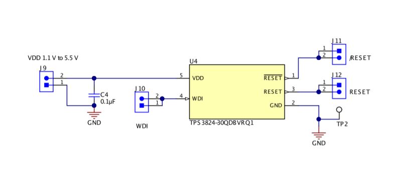
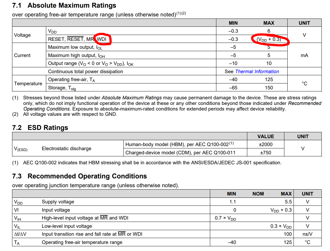
My customer is using our TPS3824-Q1 for their WDI design and they are using our TPS3824-Q1 evm.

They don't get the correctly reset signal after the end of WDI signal. The fail rate is pretty high.

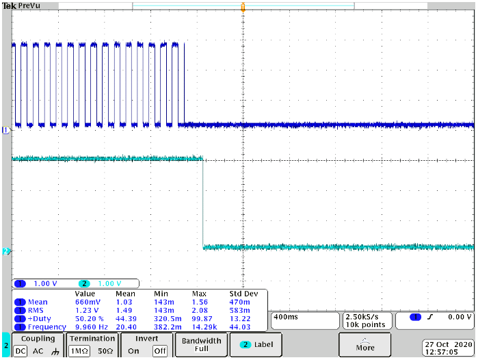
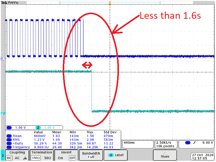
Please refer the pass case and fail case as below figure. May I have your help to understand why there is no reset signal? Thanks.

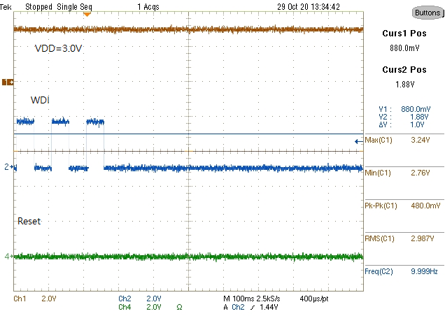
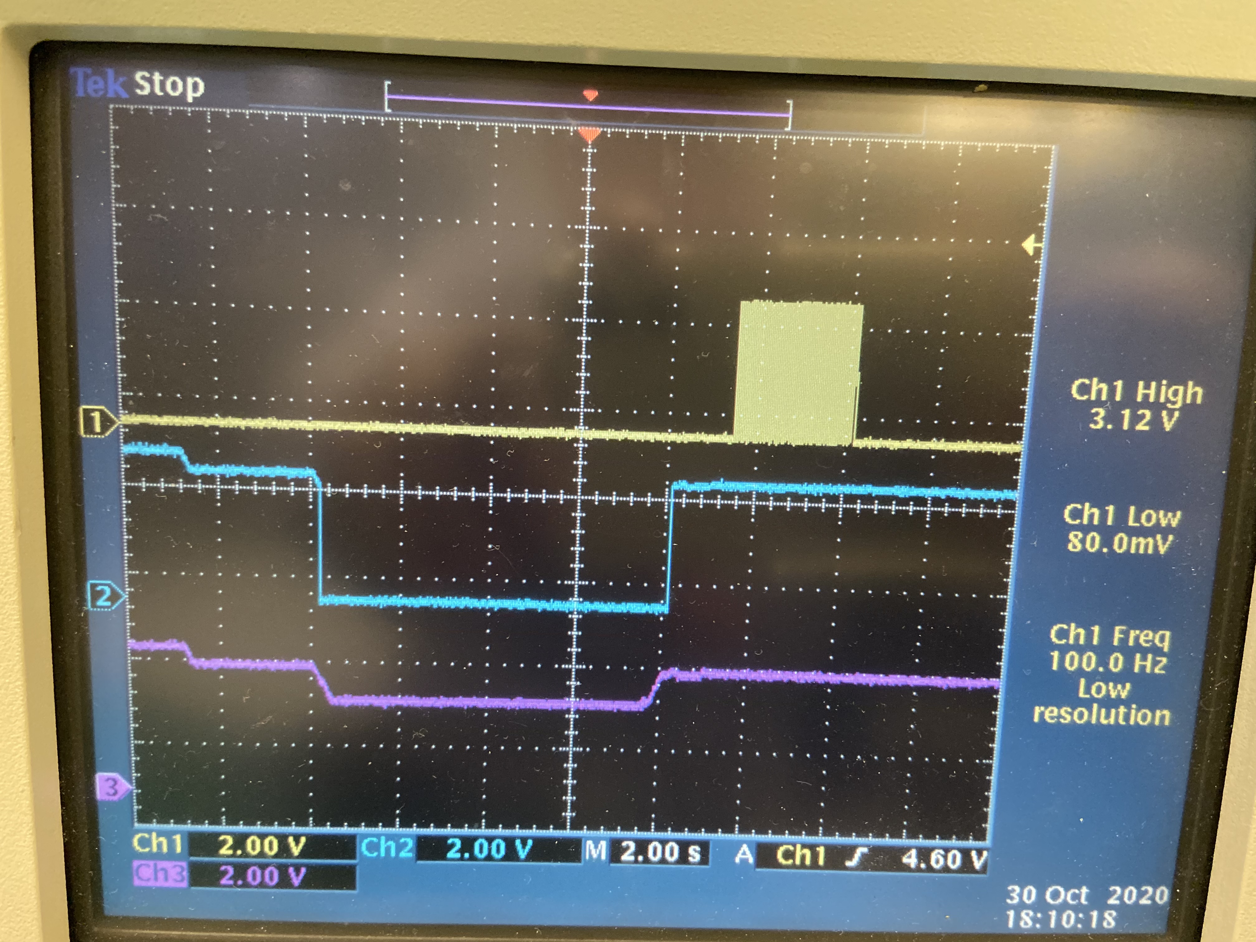
Fail: CH1 WDI, CH2 reset, Reset pin doesn't assert low 

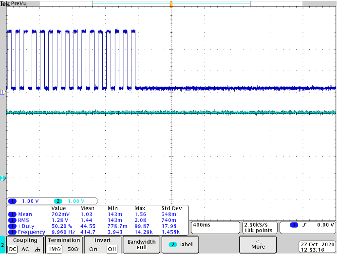
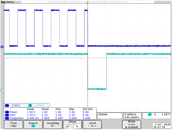
pass: CH1 WDI, CH2 reset, Reset pin assert low 

  • Hi Feng,

    Can you confirm with me if the customer is using the TPS3824-Q1?  Base on the datasheet, the watchdog time out should be 1.6seconds but the oscilloscope photos shows something different.  See below:


    Is it possible that you can share a schematic?  Also, can you get scope photos on VIN and /MR signals?

    Ben

  • Hi Ben,

    They are using our EVM to do this test and they tested TPS3824-30Q1.

    Which is shown below. There is no MR pin for 3824 and I assume Vin is VDD. And, I am asking the waveform including VDD, WDI, Reset from customer.

  • Hi Feng,

    Please keep me posted on the customer's findings.  Again, they scope photo does not make sense to me because the ttout is not correct.  I suspect they are not understanding how the part behaves and performs.  If possible, can you ask them to provide a scope photo of VDD, WDI, and RESET on one scope photo.  One more thing, it appears that the scope photos are showing /RESET and not RESET.  

    Ben

  • Hi Ben,

    Thank for your help. I couldn't  explain the behavior with customer.

    Please refer the waveform with VDD, WDI and reset signal. And, the power-up sequence is VDD first and start to provide the WDI signal. Is there any timing requirement for WDI signal? Thanks.

  • Hi Feng,

    When is the customer capturing the scope photo?  Is the scope photo taken right after the part is turned on?  Can the customer get similar results like the diagram shown below?

    Ben

  • Hi Ben,

    Thank for your help.

    We have tried to duplicate the waveform of datasheet but we  couldn't make the reset of TPS3824 issue the active low after the WDI signal stay low for a while.

    Would like to confirm with you whether we have misunderstanding the function of WDI. Does WDI signal need to synchronize with reset signal or there is anything we miss?


  • Hi Feng,

    According to the scope photo, I would recommend swapping out the TPS3824 for a new device.  I want to know if the device is causing the issue.  The IC seems to not function correctly. 

    Ben

  • Hi Ben,

    Just discussed with customer and he mentioned that he has changed serval times of TPS3824. I also would like to highlight about the test method that they are using now. They use the function generator for WDI signal. I have seen that WDI VP-P will be higher than the predicted value as below figure.

    Would you think it will induce the Sillicon into irreversible fail? If so, how do we confirm the amplitude will not damage the sillicon and also check the WDI function? Thank for your kindly help. 

  • Hi Feng,

    Thank you for the scope photo.  Regarding the input signal to the WDI pin, the input voltage to the WDI is above the Absolute Maximum Ratings (ABS max).  This operation may/will inflict irreversible damage.  Do you know why they are driving the WDI pin to above 6V?  Is the VDD voltage at 3.3V?  The WDI input should not be higher than 3.3V + 0.3V, base on the ABS max rating.

    In order to ensure the functionality of TPS3824, please instruct the customer to not go above the ABS max ratings.  TI cannot guarantee the functionality and performance of the device if any of the pins go above the ABS max rating.  See below the ABS max rating for TPS3824.  

    Ben 


  • Hi Ben,

    Do you know why they are driving the WDI pin to above 6V?  Is the VDD voltage at 3.3V?

    I think it is because they use function generator to produce the WDI signal and it is induced by impedance mismatch.

    I also see the similar behavior in our lab . The realistic measurement of Vp-p of WDI is higher than the setting of function generator. If it is the case, it will be a little hard for customer doing the evaluation because we couldn't confirm the voltage level that we provide for WDI.

  • Hi Feng,

    Can you have the customer hook up the function generator to the oscilloscope first to ensure that the voltage applied to the WDI pin is equal to VDD or 0.7*VDD?  Also, please check the function generator settings. 

    Ben