This thread has been locked.

If you have a related question, please click the "Ask a related question" button in the top right corner. The newly created question will be automatically linked to this question.

LM3492HC: LM3429HC application question and schematic confirm.

Part Number: LM3492HC
Other Parts Discussed in Thread: TPS92691, LM3492, TPS92692

Hi TI Support team,

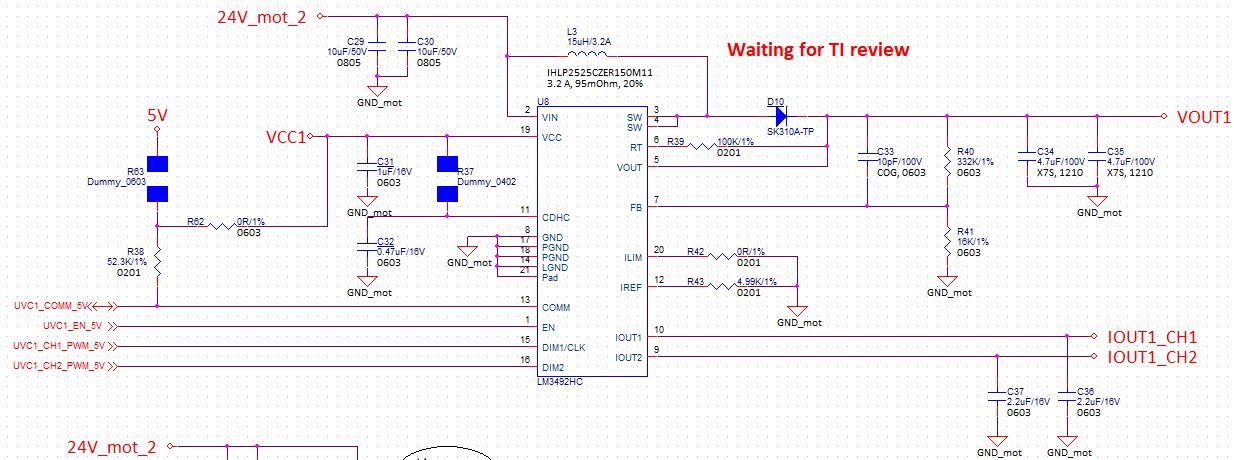
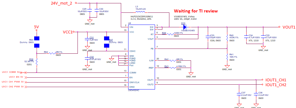
CTM use LM3492HC for they UVC LED application. The block diagram will be like this:

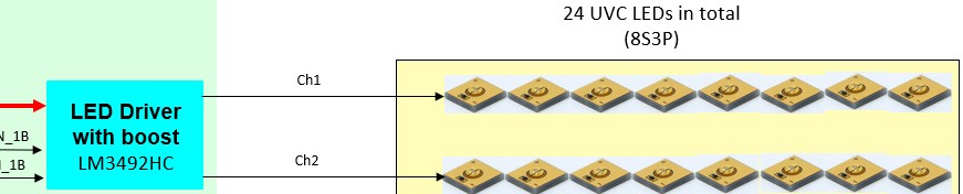
UVC LED performance are shown as below:

VF(typ.) = 6.5V @ 0.25A


The following is CTM design calculation process for your reference.

Please help review the schematic, if you have any concern just let me know.


▪ VIN(min.) = 20V, VIN(max.) = 30V

▪ VF(typ.) = 6.5V @ 0.25A

▪ VIOUT(min) = 1.25V

→ VOUT(nom.) = 8 x VF(typ.) + VIOUT(min) = 53.25V


▪ VOUT(max.) = 62.63V @ VFB(max.) = 2.88V

▪ VFB(nom.) = 2.448V @ VOUT(nom.) = 53.25V

→ RFB1 = 332KOhm, RFB2 = 16KOhm

▪ VIN(min.) = 20V, VIN(max.) = 30V


▪ FSW = 900KHz, RRT = 100KOhm

▪ VIN(max.) = 30V, ILED = 0.25A, VOUT(nom.) = 53.25V

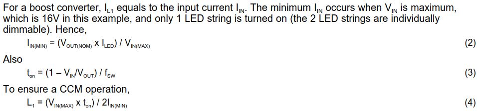
→ IIN(min.) = [VOUT(nom.) x ILED]/VIN(max.)

       = 0.44375A

→ tON = [1 - VIN(max.)/VOUT(nom.)]/ FSW

   = 0.49µs

→ L = VIN(max.) x tON/ 2 x IIN(min.)

   = 16.5µH

▪ RIREF = 4.99KOhm @ 0.25A

  • Hello Kevin,

    Recommended operating range is 50 mA to 200 mA, this is beyond that at 250 mA.

    Feedback resistors set the maximum output voltage when Vfb is 2.5V.  DHC range is recommended to be 1.05V to 2.0V.  Your values set Vfb too low.  Vfb should be 2.5 when Vout is 62.63V according to your numbers.  Note that this is close to absmax, tolerance of parts and transients may cause issues.

    Iin is not calculated correct, there are two channels, not one.  Input current is also higher at Vin(min).

    Rt should be around 140 Kohm for 900 KHz.  This will have to be measured since the output voltage is high which causes the switching frequency to increase.

    D10 is not a good diode, it is not good at elevated temperatures and the junction capacitance is high which will cause additional switching loss.

    We don't recommend running the device as calculated.  The LM3492 can be set up to run one channel at 250 mA by combining the outputs, this sets the channel currents to 125 mA.  There are other parts that can be used as a boost such as the TPS92691 and TPS92692.

    Best Regards,

  • Hi TI support team,

    For 250 mA, the content of datasheet is as follows:

    It says the LM3492HC can support 250 mA per channel. Can you confirm it.

    For Iin(min), the content of EVB datasheet is as follows:

    It says the min. Iin occurs when Vin is max and only 1 string is turn on. Can you confirm it.

    Revise the design according to other suggestions as follows:

    VFB(nom.) = 1.82V @ VOUT(nom.) = 53.25V  

    RFB1 = 453KOhm, RFB2 = 16KOhm

    ▪ FSW = 900KHz, RRT = 140KOhm

    D10 change to VSSB310-M3, Vishay

    VRRM = 100V, IF = 3A, Tj = -40~150 degree, junction capacitance =230pF


  • Hello Kevin,

    Yes, I was not looking at the 'HC' version of the part, it is rated up to 250 mA.  Iin min is calculated with only one string on at Vinmax.  Maximum input current  is calculated with two channels on at Vinmin.  Note that this design is running maximum current at maximum switching frequency and high output voltage.  The LM3492 will need good heatsinking and this circuit may run hot.

    Vfbnom sets the divider to allow the LM3492HC to run beyond absmax.  If you are using 16K at the bottom I would start with 365K ohm for the top resistor, maybe start lower to make sure Vout doesn't reach absmax.  365K and 16K set the maximum output to approximately 60V.  The LED string voltage puts this is in a narrow operating range and may be difficult to make work over all conditions.

    The diode choice is better for this application.