This thread has been locked.

If you have a related question, please click the "Ask a related question" button in the top right corner. The newly created question will be automatically linked to this question.

LP87561-Q1: Doubt on over voltage protection

Part Number: LP87561-Q1

Hi,

Will the over voltage monitoring functionality using POWER GOOD work even if the sense line (connected to FB_Bx) is floated?

Say I've enabled the over voltage monitoring functionality for PGOOD. If by mistake, in the 4-phase single output operation case, if the FB_Bx connection gets floated somehow, what happens? Does the buck VOUT level rise to near supply rail levels (~5V in my case, as my BUCK VIN is 5V) and thus potentially causing over voltage related damage to the load circuit and the PGOOD behavior will be unpredictable since FB_Bx is floating, or does the overvoltage monitoring mechanism for PGOOD still function and realize that the Buck output is going into over voltage condition relative to the set voltage even if FB_Bx is floated?

Thanks,

Anoop

  • Hello Anoop,

    If the FB connection is broken during operation then it is possible that the output voltage goes to max (=VIN). If the FB is not connected to the Vout the device cannot sense the output voltage. Actually in this case the FB voltage most probably goes to 0V and trigger PGOOD, but it does not shut down the buck. Buck still tries to increase the output voltage to reach the target. 

    If the FB connection is broken before turning on the converter, it will prevent the buck from starting. At the beginning of the soft start period the connection is checked and if the device notices that there is no current going from FB to Vout, it will stop.

    Thanks.

    Regards,

    Tomi Koskela

  • Hi Tomi,

    Thanks yet again for the quick and detailed response here.

    I added the following modifications to try and mitigate some of the concerns here with a floating sense line in the remote sense case as well as a couple of measures to try and improve the stability in the remote sensing case (Use case is single 4 phase output mode). If you could weigh in on these it will be of great help:

    • Addition of a weak short between the FB_B0 and VOUT_0 (local) lines respectively as well as FB_B1 and GND (local) lines respectively using a 1kohm resistor, in order to try and prevent the buck output from railing out to 5V if the sense lines are open by providing a pseudo local sense.
    • Addition of an RC compensation scheme wherein I have 10 ohms in series on the remote sense lines connected to FB_B0 and FB_B1 respectively and a 0.1uF capacitor between the FB_B0 and VOUT_0 (local) lines respectively as well as FB_B1 and GND (local) lines respectively, so that for fast transient voltage variations at the supply drive outputs, the sensing mechanism will act more like a local sense approach for higher frequency components (the shunt Cc caps provide the local AC feedback path) and for lower frequency components the remote sense operation gains dominance (This is a compensation method that I saw recommended for certain off the shelf power supply instruments which support remote sensing)

    A snapshot of the schematic configuration section with both the items above is shown below (the resistors and capacitors mentioned above are encircled in red) and a few PSPICE simulation results for these test cases are given below that:

    A few PSPICE simulation results for these test cases:

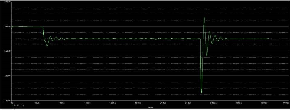
    Without RC compensation (1k weak short present between REMOTE SNS+/- and local VOUT/GND respectively)=> More transient ringing observed at load transient steps:


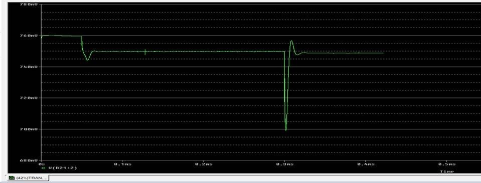
    With RC compensation (1k weak short present between REMOTE SNS+/- and local VOUT/GND respectively) => Less transient ringing observed at load transient steps:


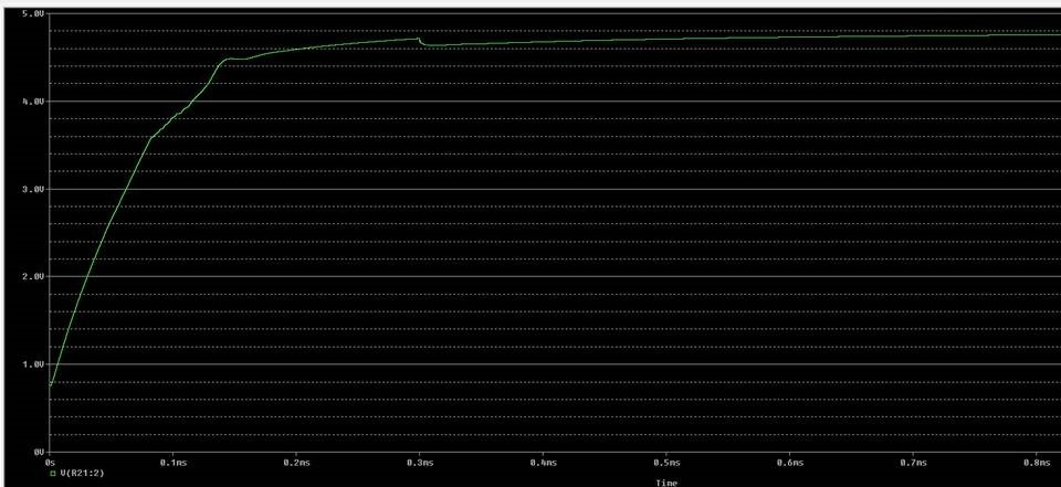
    Output with remote sense lines floating and WITHOUT the 1k weak short present between REMOTE SNS+/- and local VOUT/GND respectively=> VOUT shoots to Buck supply rails ie ~5V:


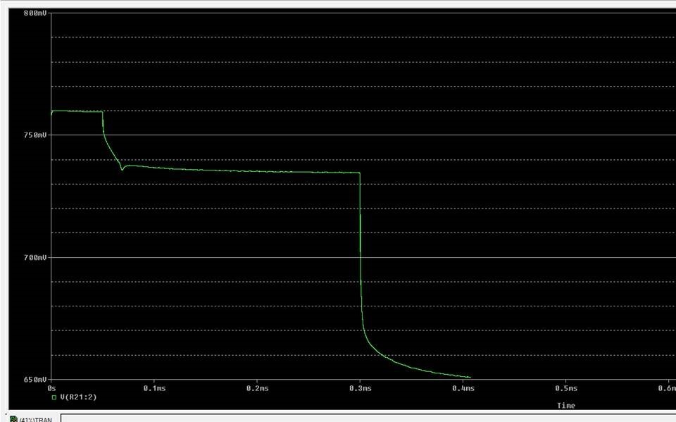
    Output with remote sense lines floating and WITH the 1k weak short present between REMOTE SNS+/- and local VOUT/GND respectively=> VOUT DOES NOT shoot to Buck supply rails and stays near to the acceptable range (even though we can see the expected IR drop with remote sensing due to the parasitic PCB and connector contact path resistance):


    Thanks,

    Anoop


  • Hi Anoop,

    I don't see problems with the additional 1k resistor as additional safety measure.

    For adding extra RC compensation circuit you need to keep the R as small as possible to avoid voltage shift and also not to have problems with the resistive pull-down at shutdown. At shutdown the output capacitors are discharged with 230ohm internal resistor connected to FB pin (when output voltage is below 0.6V). In active operation the current through FB pin is in uA range, so I don't see issues with 10ohm resistor affecting voltage accuracy.

    Anyway it is best to try out the operation on bench in addition to the simulations to see there are no surprises in startup/shutdown or stability/load transient.

    Thanks.

    Regards,

    Tomi Koskela 

  • Hi Tomi,

    Yes, we are designing a Proof Of Concept evaluation board with these measures (which is almost done), will be testing out the functionality with that first before deeming it fit for final use

    Thanks for all the valuable feedback with respect to our design with this buck!

    Thanks,

    Anoop