This thread has been locked.

If you have a related question, please click the "Ask a related question" button in the top right corner. The newly created question will be automatically linked to this question.

TPS752-Q1: GND/Heatsink Pin Connection

Part Number: TPS752-Q1

Hi Team,

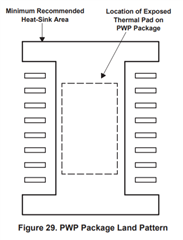
Seeking your assistance in verifying if the pins  1, 10, 11 and 20 of the TPS752-Q1 (PWP package ) are indeed internally connected. Asking this as one of our customer has reported that they have performed continuity tests on multiple TPS75201QPWPRQ1 ICs but found that there are no connections between these pins. The pins appear to be disconnected as well with the thermal pad, contrary to the note on page 22 of the datasheet. The only pins that result internally connected are respectively 3, 4 and 8, 9.

Is this a possible isolated case on a certain batch? Please help us check and verify.

Thanks in advance!


Kind Regards,

Jejomar

  • Hi Jejomar, 

    I will look into the bond diagrams for you tomorrow, thank you. 

    Best,

    Juliette

  • Hi Jejomar,

    Pins 1, 2, 10, 11, 12, 13, 14, 15, 16, 18, 19, and 20 are not internally connected. 

    Best, 

    Juliette

  • Hello Juliette,

    Many thanks for looking into this. We've shared your response with our customer and at this point they're having another doubt regarding the functionality of pins 1, 10, 11, 20 (named GND/HEATSINK). If these pins are not internally connected among them and with power pad, so what is their functionality in terms of thermal optimization?

    It seems that they would be employed as "NC" pins so they don't implements any HEATSINK (as suggested in the datasheet). In other words, if they were to include them in the heatsink area (see attached figure) or not, it won't make any difference in terms of thermal transfer of internally dissipated power. Is our understanding correct?


    Kind Regards,

    Jejomar


  • Hi Jejomar, 

    I don't have any parts with me, but when you check the continuity between the corner pins - is it open or closed?

    There's a chance that they could be connected directly to the Die Attach Pad (which is why I did not see any bond wires in the diagram). 

    If they are not connected to each other, then they provide no thermal relief. 

    Best,

    Juliette