This thread has been locked.

If you have a related question, please click the "Ask a related question" button in the top right corner. The newly created question will be automatically linked to this question.

BQ2961: Review and feedback for LiPo protection circuit

Part Number: BQ2961
Other Parts Discussed in Thread: BQ7718, BQ2947, BQ7716

Hello,

I have designed my first LiPo battery circuit and I need some input to check if this circuit is safe and protect the LiPo and the circuit from any damage. Please take a look at the snippet:

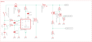
I use two LiPo batteries and the input voltage is converted to my supply voltage (this part is not shown). The circuit doesn´t contain a charging circuit, so I skipped a battery guard with overvoltage protection and simply use the BQ2961 (BQ296106) because of its Undervoltage protection.

NOTE: I don´t want to use the internal regulator of this chip, so I disable it (I think I disable it - correct me if this part is wrong) to save a little bit of current. The MOSFET "Q201" is used as reverse polarity protection and I use "F201" as thermal protection. The parts behind the fuse are used by the battery voltage measurement circuit.

So my circuit contains:

- Reverse polarity protection
- Thermal protection
- Undervoltage protection

Do I need other safety features to protect my circuit and my LiPo battery?

Thank you for your help and your ideas Slight smile

Best wishes

  • Hi Daniel,

    It looks like your image was not posted successfully. Can you try to attach it again?

    Thanks,

    Matt

  • Hello Matt,

    I´m sorry. I have uploaded the image again.

  • Hi Daniel,

    The BQ2961 and similar protectors are designed to operate with VDD connected while cells are connected, typically at all times.  See figure 9-1 or 9-2 in the data sheet.  The VDD should be connected to the unswitched cells.  Disconnecting VDD does not violate abs max as stated, but specifications for performance and currents are with VDD in the ranges shown.

    The BQ2961 does not have a regulator disable, the pin is not available in the available packages in the data sheet.  The regulator is always enabled with cells either below VUVQUAL or above UV (+ hysteresis).  For normal cell voltages the regulator should have a capacitor.  For a device without a regulator you might consider the options from the BQ2947, BQ7716 or BQ7718 families.

    When the BQ2961 (or similar OV protector) goes to OV OUT will go high shorting the cells through Q201 if the switch is closed. Be sure Q202 can handle the power.  The short will also drop the voltage for VDD of the protector causing the drive voltage to Q202 to drop.  Some oscillation may occur or heating and damage of Q202.  More normally Q202 would operate a controlled protector fuse or signal some other switch to open the path to the cells rather than short the cells.  

    Q201 may not provide the reverse polarity protection against a connection of a negative voltage at LIPO.  The body diode will allow discharge current even with low gate voltage..  Check the operation carefully for your intended operation

    A PTC device is often used as a resettable fuse, current through the part above a threshold heats the device and causes a high resistance.  Check with the device manufacturer for performance and trip with temperature behaviors.

    Check the requirements for your industry to see what protections may be required for the equipment you are designing.  Test any circuit for proper operation.  

  • Hello,

    thanks for your replay. I have talked with an FAE from TI before I design the first version and this guy told me that I can disable the internal regulator (but I had the feeling that the guy doesn´t understand my problem very well, so I was pretty unsure after the discussion). I think the answer from this guy wasn´t correct, because a component burns down after powering up the PCB and I believe that component was the battery guard.

    I will apply your changes Slight smile. Many thanks.