This thread has been locked.

If you have a related question, please click the "Ask a related question" button in the top right corner. The newly created question will be automatically linked to this question.

TPS65400-Q1: Output 1 does not regulate/switch most of the time across multiple parts

Part Number: TPS65400-Q1

I have a design in which I use the first three outputs of this chip, and output 1 will randomly work or not work.  Each time the chip is powered up, or the output is switched on through ENSW1, there's a random chance that it will work correctly.  When it is not working, the comp node will be at 0.476V instead of 0.8V, and the output will be about 5V.  This output will be maintained even if I turn the other channels off through their ENSW pins.  The switch node is a constant DC value.  This output seems to have an impedance of about 3 ohms based on a load test with a small resistive load.  The chip will quickly warm up even with a small load because it is essentially acting as a linear regulator.  There's a second one of these chips on the board with the exact same layout, but different feedback resistors and I2C resistor.  That chip works perfectly.  I have checked the passives for the first chip extensively and there's nothing wrong with them.  I have also replaced the chip twice with brand new parts, and the problem repeats itself in the exact same fashion.

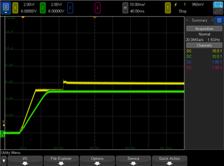
The following is a startup transient of the bad chip.  Yellow is the output 1 voltage (set for 8.5V), green is the output 3 voltage (set for 5V).  Both start correctly, but output 1 abruptly stops rising at 5V.  The voltage increases again when the regulator appears to retry the startup, and this will fall back down to 5V over the course of a few seconds.

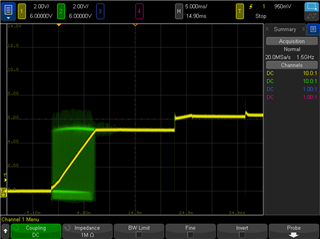
Here's another view, with green now showing the switch node.  The switch stops once 5V is hit.  Two singular pulses to 0V can be seen after the initial climb, and the output voltage bumps higher when this occurs.

I was not successful in capturing a working startup transient.

  • Hi, Erik 

    1. Could you send the schematic for reviewing? 

    2. It looks the Vout is limited by Vin. 

    Could you measure the Vin, Vout1 and LX1 waveforms at the same time? and Zoom in.  

  • Hi Zhao,

    1. Here's the schematic of non-functioning chip

    2. That's not the problem.  In all of these tests, I used 12V from a high quality power supply.  I have previously verified that the supply is correctly outputting 12V on an oscilloscope during the startup.  I admit, it does look like that based on the switching node waveform, but that 5V is the same as the 5V the output will eventually get to.  From the schematic, you can see a 6V output, which works correctly during the fault.

    Unfortunately, it's a new day and the bad chip has decided it wants to work 100% of the time now.  I put the board through an ultrasonic cleaner and it's still fine.  Maybe the chip doesn't work for a day after reflow, but that's inconsistent with the original chip I tried (which had the issue for weeks). The original chip is also the only one that went through a well controlled reflow cycle.

    I will update if the problem comes back.

  • Hi, Erik 

    I suspect this issue was caused by Vin slow rising, so I asked you measure the Vin, Vout1 and LX1 waveforms at the same time. 

    When Vin > UVLO rising threshold, IC will start switching, Vout start to ramp up, but if Vin is too slow, it will limit Vout1 to the target voltage and trigger UVP(hiccup). 

    Suggest to do the power cycle test, and measure these waveforms in one picture.