This thread has been locked.

If you have a related question, please click the "Ask a related question" button in the top right corner. The newly created question will be automatically linked to this question.

TPS3828: How to handle the chip during development/ debugging?

Part Number: TPS3828

Hello there,

I am considering to replace the software watchdog with an external watchdog like TPS3828-33-Q1 in our design. I find the software one implemented in the MCU not so reliable.

When thinking about this a question arises in my head. For example, lets cosider this example schematics from the datsheet:

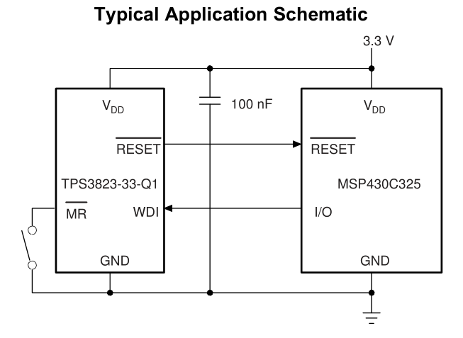
Normally the #RESET line of the SWD/JTAG probe would be connected to the #MR line. The question is: what is the official way of handling this chip during software development or debugging? If I place a breakpoint in my code, that means the WDI signal will stop toggling, thus, the TPS3828 chip will reset my MCU... Since the probe is connected to the #MR line, not #RESET, I cannot really disconnect any circuitry for development. Seems like there should be an #ENABLE line available in the TPS3828 chip.I thought of multiplexing the WDI line with the probes CLK signal but that line is not always toggling (ie when stopped on a breakpoint and not reading anything), so this wouldnt work. On the other hand the TPS3828-33-Q1 model has open-drain as #RESET. In that case I could hardwire #MR to VCC and physically disconnect the #RESET line only from the TPS3828-33-Q1 chip (ie. using a jumpoer, N mosfet etc), leaving the probes #RESET line connected with MCU #RESET line. But this seems a bit of a hack than solution...

This one bugs me. I would appreciate all help regarding this issue.

  • Lukasz,

    For the TPS382x family of devices, if you leave the WDI floating (disconnected or high impedance), the device will generate its own WDI signal to prevent the Watchdog from causing a reset. This means that before you place a breakpoint in the code, set the WDI pin for high impedance, then the device will generate its own WDI signal and prevent reset, then you can begin toggling when the break point ends. This is the only way to disable the reset caused by WDI is to leave WDI pin high impedance.

    Please let me know if this will solve your problem.

    -Michael
  • Hi Michael, thank you for answer.
    Remembering to put the IO state in high impedance state each time I want to place a breakpoint would be not very convenient. But from what you are saying it seems that I can physically disconnect the WDI pin from the MCU. If for example the WDI signal would be connected to the MCU through a jumper, I could always remove it. Am I right?
    Also, is this self WDI signal functionality working always? I mean- No matter at what point during the device operation the other end of WDI signal is put high impedance, it will start "self oscillating"?

    Also, for this device, what load maximum load would it consider high impedance? Is there I threshold? I fear of some parasitic pull-up/ pull-down currents that would fool the the device.

  • Lukasz,

    Yes you are correct. Physically removing the WDI pin from the MCU will work meaning when you remove the WDI pin and leave it floating, the device generates its own internal WDI signal to prevent reset. The self WDI signal functionality always works meaning at any point you can disconnect the WDI pin and the device will switch over to its own internal WDI signal.

    We do not specify the load threshold to be considered "high impedance" but our tests use resistance load of 1Meg ohm at capacitance 50pF, so I imagine if the load impedance is larger than 1Meg ohm, this and the current sink is lower than the "low level average current" of 15uA, I believe this would work. Using a jumper or switch as you mentioned is the preferred method to "disconnet" WDI pin from the rest of the system to get the WDI pin to a definite "high impedance" state. Please make sure you test the WDI, RESET functionality when trying to get WDI in "high impedance" if not actually disconnected the pin.

    Please let me know if you have any additional questions or need any additional support. Thanks!

    -Michael
  • Hi Michael,

    Thank you for detailed answer. Seems like jumper/ switch would work perfectly indeed. But the end preffered method would probably be to be able to switch the functionality in software. From you description it seems like all I need to do for that on the MCU side, is to configure the normally output WDI pin as input without pull down or up, and it should work.