This thread has been locked.

If you have a related question, please click the "Ask a related question" button in the top right corner. The newly created question will be automatically linked to this question.

LM5017: LM5017 failure mode - "VIN" pin burning and melting package/PCB trace

Part Number: LM5017
Other Parts Discussed in Thread: UCC27211

Hello,

I seem to be having a similar issue to this post from 2013, however I haven't been able to get a hold of him to ask if his fix worked:

https://e2e.ti.com/support/power-management/f/196/t/273008

I have an LM5017 powered off 44-51V and its output is connected to the primary coil of a transformer to give 3 isolated 14V outputs. This is for a 3-phase motor drive application and the outputs are powering TI UCC27211 high/low side gate drivers.

The motor drive works for for the most part, but every now and then (I don't know how to replicate the failure) the LM5017 will just pop and we will see a hole in the package near the VIN pin or the pin burned off. This only happens on a "start" condition when the gates begin to switch/FETs begin to turn on. The last one was bad enough to actually delaminate the 1oz trace on our PCB!

My gate drive circuit is 3x of these:


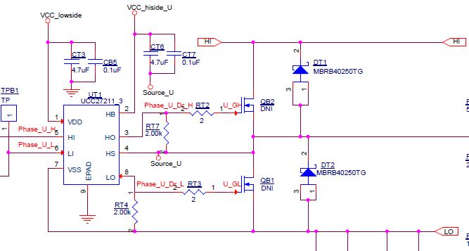
Has anyone had a similar failure with this part or is there an applications engineer for this part that can shed some light on what events cause this type of failure? I have had 6 LM5017 chips fail so far in the same manner.

Thanks,

Vishaal Varahamurthy

Electrical Engineer

LaunchPoint Technologies

  • Hello Vishaal,

    Failures like this are typically due to electrical over stress, I assume this is happening at turn on of the input supply being supplied to Vin of the LM5017.

    Looking at your schematic I cant see your input caps or your input filter.

    First make sure you have input cap (ceramic) close to Vin and Gnd.

    Also check if you are using an input filter and ensure it is well damped by placing a higher capacitance in parallel with the input Ceramic with an ESR high enough to dampen the parasitic inductance or inductance formed by input filter (inductor).

    See link below for more details.

    www.ti.com/.../snva538.pdf


    Hope this helps?
  • Hi David,

    Thanks for the input filter suggestion, I'll attempt to add one of thiose as well. I have approximately 220uF of capacitance on my DC bus.

    However, I've never had the failure occur at the turn-on of the input supply to VIN. It only happens when gate drivers begin to switch the FETs. That is to say I have always been able to power on the DC bus (which powers VIN) successfully without any issues. 

    Could it be that the lack of an input filter is causing the LM5017 to get loaded down too much during the transient when its output begins to get loaded?

    A bit more info:

    - The LM5017 only fails when the FETs *begin* to switch, and never fails if I have already begun to switch and my motor is running. The failure is inconsistent and I don't know how to replicate it

    - LM5017 is not under heavy load when the failure occurs. I have had this happen mostly when the chip is at a cool 35-40C 

    Best,
    Vishaal

  • Are there any known failures that happen when the device is already powered up and its output begins to get loaded?
  • Hello Vishaal,

    As previously mentioned if Cin ceramic is not close to the IC, then there is a potential of ringing to occur and a potential overshoot can occur and EOS to the device.

    From the photo the Cin looks too far. Please kludge next to the Vin and Gnd and retest.

    Hope this helps?