Because of the holidays, TI E2E™ design support forum responses will be delayed from Dec. 25 through Jan. 2. Thank you for your patience.

This thread has been locked.

If you have a related question, please click the "Ask a related question" button in the top right corner. The newly created question will be automatically linked to this question.

BQ76930: Design help needed for BQ76930 based BMS

Part Number: BQ76930
Other Parts Discussed in Thread: BQ78350, BQ78350-R1

Hi

I’ve posted a few times about designing a BMS for a LiFePO4 battery (BQ78350-R1: bqStudio is not showing cell voltages, BQ76930: Design help requested for BQ76930).

I’m now at the stage where I could really use some help with the detailed design. As was suggested during an earlier post on this forum, I went and purchased the BQ76930 Evaluation board (and BQ2400 interface module). After a few false starts, this is now running and I’m able to query and set registers as well as observe the fuel gauge behaviour when the board is connected to my battery pack.

Here are the details of my 8s8p battery pack.

Constructed using Headway 38120 cells which have the following specifications:

  • 10C discharge

  • Voltage: 3.2V nominal, 2.5V min, 4.2V max

  • Charging Voltage: 3.65V

  • Cut-off Discharge Voltage: 2.0V

  • Charging Method: CC/CV

  • Maximum Discharge Current (continuous): 100A

  • Maximum Charge Current (continuous): 50A

Using the above values, the 8s8p battery pack has the following characteristics:

  • Voltage: 25.6V nominal, 20V min, 33.6V max

  • Charging Voltage: 29.2V

  • Cut-off Discharge Voltage: 16.0V

  • Charging Method: CC/CV

  • Maximum Discharge Current (continuous): 800A

  • Maximum Charge Current (continuous): 400A

Battery Pack is nominal 24V, 80AH.

The largest current draw will be a starter motor that draws approx. 200A. (4.8KW), so I'm thinking I should design the BMS to handle 300A.

Now that I’m designing my BMS, based on what I have understood from using the evaluation board, I have some questions.

  1. The BQ76930 documentation states that it contains cell balancing FETs. Why are there balancing FETs on the evaluation board? What should I do wrt the balancing FETS? Use the BQ76930 ‘internal’ ones, or should I include ‘external’ FETs in my design?
    The one (only?) reason I can see for using external FETs is to increase the balancing current – the internal FETs are relatively limited in how much current they can shift from cell to cell

  2. What about the current sensing resistor? As I’m designing a board that will handle up to 300A, I assume I’ll need to
    a) use a suitably large resistor (small R but big W)
    b) do some calibration of the gauge so that it matches the actual current being measured.

  3. Is there anything else that I should be thinking about at this point.

Cheers,

Mike

  • Hi Mike,

    You are correct that the external FETs are needed for higher cell balancing currents. The BQ76930 internal cell balancing current is not very high, so most of the reference designs also use external FETs.

    Since this is very high current, the sense resistor selection is very important to make sure the power can be handled. Some users use multiple sense resistors in parallel for higher currents.

    I'm not sure if your design will include the BQ78350, but if you are using this controller, you will need to download the BQ78350-R2 firmware which includes current scaling. The BQ78350-R1 maxes out at around 32A. 

    We can always help review the schematic when you're ready. I'm not sure if I pointed you to this already, but this video may be helpful thinking through the steps in the schematic: https://training.ti.com/how-create-schematic-bq76920-bq76930-and-bq76940

    Best regards,

    Matt

  • Hi Matt,

    Thanks for your comments and reading suggestions.

    I'll work through the tutorials and take up your offer to review my schematics as they progress.

    Cheers,

    Mike

  • Sounds good, Mike. I will go ahead and close this thread. If you have more questions or have a schematic to review, you can either start a new thread or reply to this one and it will reopen.

    Best regards,

    Matt

  • Hi Matt

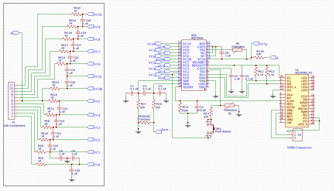
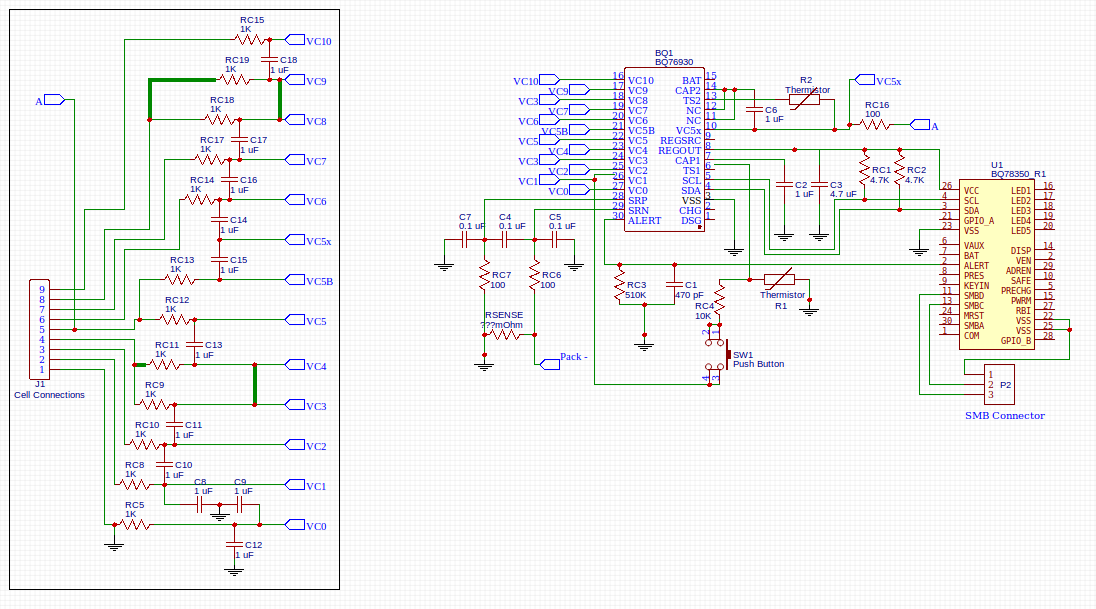
    As indicated in my earlier post, I am now working on the design for my BMS.  I would appreciate your feedback on the wiring of my cell connections shown in the attached schematics.  Although I will most likely not use the built-in balance FETs, I am trying to understand the simpler circuitry before I move on to having external balancing FETs.

    I've attached 2 partial schematics, with the focus solely on the battery cell connections for the purpose of this post.  The first schematic shows a 10 cell battery while the second shows the changes I've made for my 8 cell battery, namely the shorting of cells 3,4 and cells 8,9.

    Does this look correct?

    Thanks for your feedback,

    Mike

  • Hi Mike,

    Looks good! The cell connections for reducing the cell count are correct.

    I noticed there are two capacitors from VC0 to GND, so you can remove one of these.

    There also needs to be a diode from VC5 to VC5x and from VC10 to BAT, but I know you may not have gotten to this part of the schematic yet.

    Best regards,

    Matt

  • Hi Matt

    Thank you for your feedback and confirmation that I am on the right track with this design.

    I hadn't noticed the unwanted cap, so thanks for spotting that.  My next step is to introduce external balancing FETs, so I will study how these operate with the BQ76930 and once I've added these to the design I'll share it with the forum and look for feedback.

    Thanks very much for your ongoing support, its much appreciated.

    Cheers,

    Mike