This thread has been locked.

If you have a related question, please click the "Ask a related question" button in the top right corner. The newly created question will be automatically linked to this question.

LMG1020: Questions about the output of 1020

Expert 1015 points
Part Number: LMG1020

Hi Jeffery,

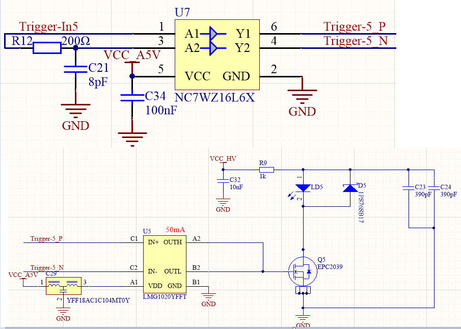
   I Ihave encountered the problem that the output amplitude of 1020 is inconsistent with the last time,the schematic is as follows:

I use the RC delay circuit(R12&C21) to generate 2ns narrow pulse input to 1020,but I found four identical circuits, some 1020 output 5v, some 1020 output only 2v, when I change R12 to 220ohm or C21 to 10pF, 1020 output above 4.5v, which makes me very confused,  I think that as long as the input of 1020 reaches the input threshold, the output should be 5v. Why does the situation I describe appear?  Can you help me confirm what caused it?

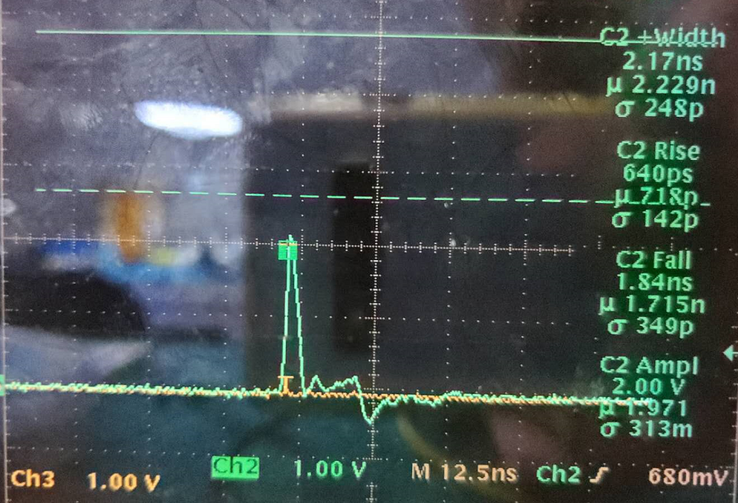
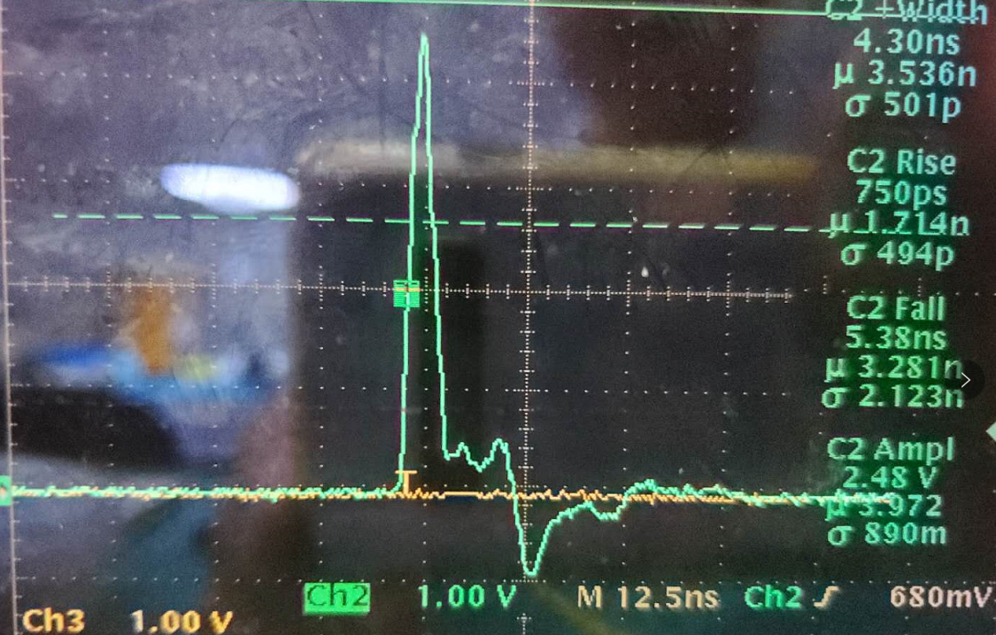
Pls look at the picture follows:for the same circuit,the difference between the two pictures is only that the value of C21 is different. The first picture is the output of 1020 at 8pF,the second picture is the output of 1020 at 10pF.

  • Hi Suy,

    Thanks for reaching out on lmg1020 and myself.

    What you are seeing is an effect of the minimum input pulse width spec of lmg1020.

    From the schematic I can see your pulse technique is to pulse IN+ and then 2ns later pulse IN- to create a 2ns pulse difference for 1020.

    1020's minimum input pulse width is about 1ns so its possible the scope measurement is not being taken from 2.5V or 50% of the 5V gate pulse making the measurement say 2ns.

    From the images the pulse width on the bottom one is about double the pulse width on the top one. This leads me to believe that changing the RC low pass filter values the input buffer will change the pulse width respectively. A larger pulse width allows the 1020 to reach 5V. A shorter pulse width only allows 1020 to reach a 2V pulse before the falling edge commands 1020 to turn the pulse off.

    Does this make sense?

    Thanks,

  • Hi Jeffery,

    Thanks for your answers.   

    Pls let me explain to you.Both IN+ and IN-  of 1020 input width are  above 20ns ,but IN-is delayed by 2ns relative to IN+,so the output of 1020 is a narrow pulse of 2ns.

  • Gotcha thanks Suy!

  • Hi Jeff,

       Today i finally found that this problem was caused by my signal generator. When the signal generator outputs a 5v 150ns pulse (the output to the oscilloscope is indeed a 5v 150ns pulse), it is output to 1020 IN+ and IN- through NC7WZ16L6X, which is also 5v 150ns  , But the output of 1020 is only 2v, if I set the signal generator to 7v and the other unchanged, the output of 1020 can reach 5v.  I still can't understand how this happens

  • Thanks Suy, to me this seems like you are inputting a very short pulse on the input to the output of 1020. This pulse is approaching the minimum input pulse width of 1ns typical. This is what is preventing the 1020 output from reaching 5V. Does this make sense?

    Thanks,

  • Yes,I think you are right.

    Thanks you